Technique for installing dental implant assembly

a dental implant and assembly technology, applied in dentistry, dental surgery, medical science, etc., can solve the problems of reducing the feasibility of a maxillary dental implant, reabsorption of the bone surrounding the sinuses, and inability to meet the needs of patients,

Inactive Publication Date: 2002-08-01
DENTOSONIC
View PDF0 Cites 12 Cited by
  • Summary
  • Abstract
  • Description
  • Claims
  • Application Information

AI Technical Summary

Problems solved by technology

It is not feasible just after installing a dental implant to then mount a dental bridge on the post to support artificial teeth.
Moreover periodontal disease may cause reabsorption of the bone surrounding the sinuses.
When a patient has experienced a substantial loss of bone, the feasibility of a maxillary dental implant is diminished with a resultant increase in the rate of failure.
Thus the bone in the maxillary dental arch of a patient having an enlarged maxillary sinus condition is usually incapable of effectively accommodating a dental implant.
The implant is therefore incapable of properly supporting a dental bridge.
This two-stage procedure and the protracted time period ent

Method used


Image

  • Technique for installing dental implant assembly
  • Technique for installing dental implant assembly
  • Technique for installing dental implant assembly

Examples


first embodiment

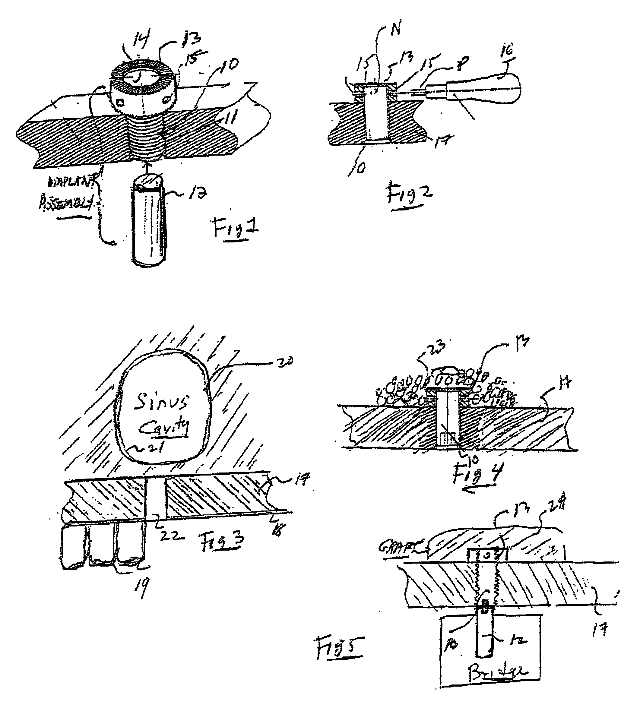
[0035] Referring now to FIG. 1 shown therein is a dental implant assembly for installation in an augmented maxilla in accordance with the invention. The assembly is composed of the following three sections:

[0036] I. Root Section 10 formed by a cylindrical metal shank having an external threading 11 with a cutting edge defining a self-tapping screw which can be screwed into a hole bored in the maxilla.

[0037] II. Post Section 12 formed by an unthreaded metal rod which is attachable to the rear end of root section 10 and serves to support a dental bridge.

[0038] III. Nut Section 13 formed by a metal nut which screws onto a nose on the front end of root section 10 and is provided for this purpose with an internally threaded bore 14. This nut acts to lock the root section in place after being screwed into the bone hole.

[0039] Normally in order to hold or turn a nut on a threaded screw, one uses for this purpose a wrench whose head is adapted to socket the nut. But to engage the nut, the h...

second embodiment

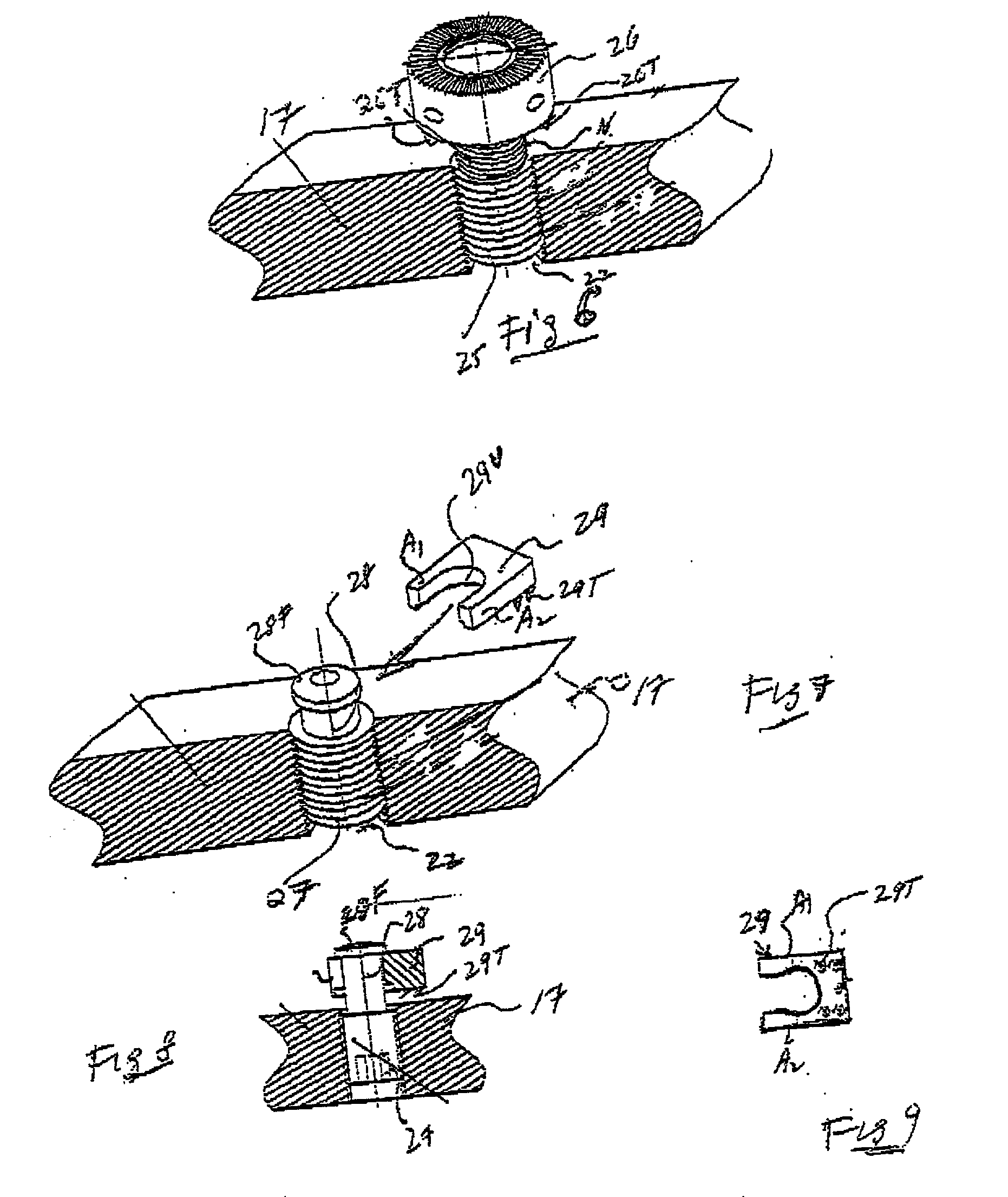
[0057] In this embodiment which is illustrated in FIG. 6, we have a self-tapping threaded root section 25 which functions as a screw that is screwed into a hole 22 drilled in maxilla 17. Projecting from the upper end of root section 25 into the sinus cavity is a threaded nose N which is engaged by a nut 26 having radial holes therein to receive the prong of tool 16 shown in FIG. 2.

[0058] The treading of root section 25 whose shank diameter matches the diameter of drilled hole 22 is right-handed (clockwise), whereas the threading of nose N whose diameter is somewhat smaller than that of the root section is left-handed (counter-clockwise). Also counterclockwise is the internal threading of nut 26 received on the nose.

[0059] The underside of nut 26 is provided with a set of sharp projections or teeth 26T capable of cutting into bone. The purpose of the differential threading is to facilitate the penetration of the teeth into the maxilla so that it becomes embedded therein to resist unt...

third embodiment

[0064] In this embodiment which is illustrated in FIGS. 7, 8 and 9, the root section 27 of the assembly which is screwed into hole 22 bored in maxilla 17 is the same as the root section 25 in FIG. 6. However nose 28 which projects from root section 28 into the sinus cavity is not threaded but is formed by a cylindrical boss whose diameter is somewhat smaller than that of the root section. On the head of the boss is a circular flange 28F of large diameter.

[0065] In this assembly, the fastening or locking element section is not a nut as in the other embodiments but a rectangular metal block 29 having a U-shaped recess 29U defining a pair of arms A1 and A2.

[0066] The underside of block 29 is provided with projecting pins or teeth 29T. This locking element is simple to install, for one has only to slide it onto boss 28, as shown in FIG. 8 so that arms A1 and A2 of the block straddle the boss and underlie flange 28F.

[0067] Then the operator us in the counterclockwise direction the root s...


PUM


Abstract

A technique for installing in the maxilla of a patient a dental implant assembly having a root section, a post section and a nut or locking element section. The root section is treaded to define a self-tapping screw which at its rear end is attachable to the post section and at its front end to the locking element section. To carry out this technique, the root section is screwed into a hole bored in the maxilla, the nose at the front end of this section then projecting into tie adjacent sinus cavity. The membrane lining the sinus cavity is lifted to admit the locking element section which is then attached to the nose to lock the root section to the maxilla. Then a charge of bone particles is deposited in the cavity to cover the nut section and the surrounding maxilla region. In a time period lasting several months, the bone particles gradually fuse with and graft onto the maxilla to augment its structure and embed the locking element section therein. Concurrently in the same period, the root section proceeds to fuse with the maxilla. This period of concurrent activity represents the total time it takes to complete the dental implant installation, after which it is feasible to mount a dental bridge on the post section.

Description

[0001] This invention relates generally to dental implants to replace missing teeth, and in particular to a method and an apparatus therefor for augmenting the maxilla of a patient suffering from bone loss and for installing a dental implant assembly therein in which the implant is anchored in bone grafted onto the maxilla.BACKGROUND OF THE INVENTION-STATUS OF PRIOR ART[0002] A typical dental implant consists of a root section that is threaded to define a self-tapping screw to which is attached a post section to support a dental bridge.[0003] Dental implants are surgically introduced into the mandible (lower jaw) or to, the maxilla (upper jaw) along the occlusal plane. It is effected by cutting through the gingival tissue to expose the bone into which a hole is then bored. The root section of the implant is then screwed into the bone hole to tap an internal thread therein. After the root section is screwed into the hole, the gingival tissue is sutured about the bone and the base of ...

Claims


Application Information

Patent Timeline
IPC IPC(8): A61C8/00
CPCA61C8/0006A61C8/0009A61C8/0092
Inventor SROUJI, SAMER M.GHRAYAB, HANNA
Owner DENTOSONIC
Why Eureka
Try Eureka