Solution to be optically treated, a method for forming an antireflection film, a method for pattern-plating and a method for manufacturing a thin film magnetic head

Inactive Publication Date: 2002-08-08
TDK CORPARATION
View PDF0 Cites 5 Cited by
  • Summary
  • Abstract
  • Description
  • Claims
  • Application Information

AI Technical Summary

Benefits of technology

[0019] It is further object of the present invention to provide a method suitable for manufacturing a thin film magnetic head having a narrowed recording track width.
[0042] Moreover, since the antireflection film is removed with the photoresist, the process to remove only the antireflection film is not required. Accordingly, the degradation of the pattern precision of the resistframe and the decrease of the height of the resistframe, due to the difference in the etching rate between the second yoke portion and the second pole portion, are prevented. Consequently, the second pole portion and the second yoke portion can be formed in their precise patterns.

Problems solved by technology

In the second magnetic film-forming process, however, an exposing light in the photolithography process to form the resistframe is reflected at the surface of the insulating film and then, the reflected exposing light reaches an area beyond a photomask-defining area and exposes the photoresist around the area, resulting in the degradations of the pattern precision of the resistframe and the second magnetic precision.
Thus, the exposing pattern of the pole portion is different from that of the photomask, resulting in the pattern destruction in a part of the resistframe corresponding to the pole portion.
The pattern destruction of the resistframe has difficulty in developing a recording density by narrowing a recording track width up to not more than 1.0 .mu.m.
As a result, the resistframe in the pole portion area is etched largely during the removing the antireflection film, resulting in the large distance of the resistframe.
In other words, the antireflection film to narrow the width of the pole portion enlarges the distance of the resistframe because of the removing process of the film, resulting in having difficulty in narrowing the pole portion.

Method used


Image

  • Solution to be optically treated, a method for forming an antireflection film, a method for pattern-plating and a method for manufacturing a thin film magnetic head
  • Solution to be optically treated, a method for forming an antireflection film, a method for pattern-plating and a method for manufacturing a thin film magnetic head
  • Solution to be optically treated, a method for forming an antireflection film, a method for pattern-plating and a method for manufacturing a thin film magnetic head

Examples


first embodiment

A First Embodiment-thin Film Magnetic Head

[0106] FIG. 6 is a perspective view of a first embodiment of the thin film magnetic head according to the present invention and FIG. 7 is a cross sectional view of the thin film magnetic head depicted in FIG. 6. In these figures, the sizes of the parts are exaggerated. The thin film magnetic head shown in these figures has slider 1 and at least one inductive type thin film magnetic conversion element 2.

[0107] The slider 1 has rail parts 11 and 12, of which substrate surfaces 13 and 14 serve as an air bearing surface (hereinafter, abbreviated to a "ABS"), on its opposing surface to a recording medium. The slider 1 does not always have the two rail parts 11 and 12, and may have one through three rail parts or no rail part. Moreover, for improving its floating characteristic, the slider may have a variety of geometrically designed opposing surface. The present invention may be applied for any kind of slider. The slider 1 is made of a ceramic ma...

second embodiment

A Second Embodiment-SA Type Thin Film Magnetic Head

[0142] FIG. 26 is a cross sectional view of a SA type thin film magnetic head in the second embodiment and FIG. 27 is a perspective view on an enlarged scale of the pole portion in the SA type thin film magnetic head shown in FIG. 26. The similar parts in FIGS. 26 and 27 to ones in FIGS. 6 and 7 are designated by the same reference numbers, respectively. In the SA type thin film magnetic head, the insulating film includes a first insulating film 25 and a second insulating film 27. The first insulating film 25 supports the coil film 23. The second insulating film 27 is provided on the base of the first insulating film 25 in the side of the ABSs 13 and 14 and defines the Throat Height=0.

[0143] Moreover, in the second magnetic film 22, the second yoke portion 221 is positioned on the first insulating film 25, its one end being connected to the second pole portion 220 continuously, its other end being coupled to the first yoke portion 2...


PUM


Abstract

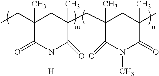
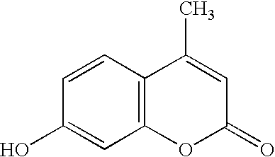
A solution to be optically treated including a cyclopentanone solvent, polymethylglutarimide and a light absorption dye is applied onto a body to be plated 100 including an inclined portion 200, and thereafter, is thermally treated to form an antireflection film 300. Then, a photoresist 400 is applied so as to cover the antireflection film. Subsequently, a photolithography process to form a plate-pattern on the body to be plated is carried out for the photoresist 400 and the antireflection film 300.

Description

BACKGROUND OF THE INVENTION[0001] 1. Field of the Invention[0002] This invention relates to a solution to be optically treated, a method for forming an antireflection film, a method for pattern-plating and a method for manufacturing a thin film magnetic head using the pattern-plating method.[0003] 2. Related Art Statement[0004] In a manufacturing method of a thin film magnetic head, normally, a second magnetic film serving as a top magnetic film is formed after a first magnetic film (bottom magnetic film), a gap film, an insulating film to support a coil film are formed on a wafer. Moreover, in the case of forming the second magnetic film, a plate-underfilm is formed on the whole surface of the wafer including the insulating film by a sputtering method, etc. Subsequently, a photoresist is applied on the surface of the plate-underfilm and is processed by a photolithography method to form a resistframe for forming the second magnetic film. Then, the second magnetic film is formed in t...

Claims


Application Information

Patent Timeline
IPC IPC(8): G03F7/09G11B5/31H01L21/027
CPCG03F7/091G11B5/3133G11B5/3163G11B5/3166
Inventor KAMIJIMA, AKIFUMIHOKUSHIN, JUNICHI
Owner TDK CORPARATION
Why Eureka
Try Eureka