Multiplex communication

a multi-channel communication and multi-channel technology, applied in the field of multi-channel communication, can solve the problems of significant frequency shift, ambiguity cannot be accepted, and frequency estimates

Inactive Publication Date: 2002-08-22
INMARSAT
View PDF0 Cites 131 Cited by
  • Summary
  • Abstract
  • Description
  • Claims
  • Application Information

AI Technical Summary

Benefits of technology

[0015] Thus, there is a spread in time over which the reference symbol is transmitted, which may under some conditions improve the protection of the reference symbols to impulse or short burst noise.

Problems solved by technology

However, this technique results in frequency estimates which can be ambiguous by multiples of the reference symbol repetition frequency (the reciprocal of the reference symbol repetition period).
Such ambiguity cannot be accepted under all circumstances whilst acquiring frequency, particularly in satellite communications where the Doppler effect due to satellite movement in non geostationary orbits can result in significant frequency shifts.
However, this imposes an additional delay whilst samples are accumulated in order to derive the average.
However, the (sin x / x) spectral shape of the OFDM subcarriers results in a very large number of relatively high amplitude sidelobes extending beyond the centre frequency of the lowest frequency subcarrier and the centre frequency of the highest frequency subcarrier.
These sidelobes cannot simply be eliminated by brick wall filtering, because this would degrade the orthogonality of the signal, resulting in co-channel interference at the receiver.
This can cause either overload, and hence distortion and loss of orthogonality, at the transmitter, or excessive back off of the transmitter or satellite power amplifiers if automatic gain control is employed, which may reduce signal reception unacceptably, or reduce the level of other signals transmitted through the same amplifier.
This measure alone can lead to unacceptable distortion.
Where this process is insufficient to reduce the magnitude of all subcarriers, the second process reduces the magnitude of those temporal portions (e.g. samples) which are still excessively powerful (e.g. by clipping them to a predetermined threshold).

Method used


Image

  • Multiplex communication
  • Multiplex communication
  • Multiplex communication

Examples


Embodiment Construction

[0069] System Overview

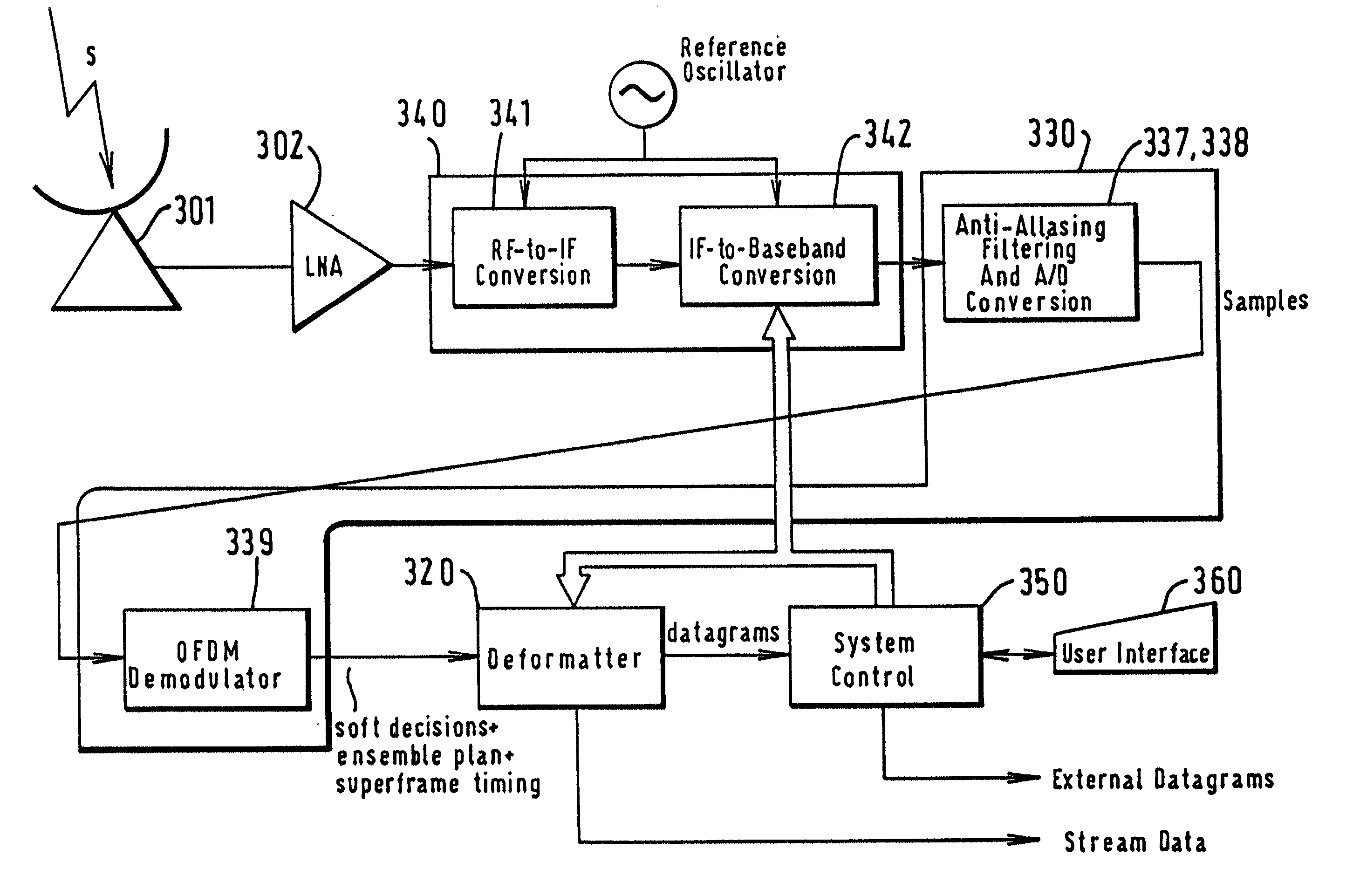
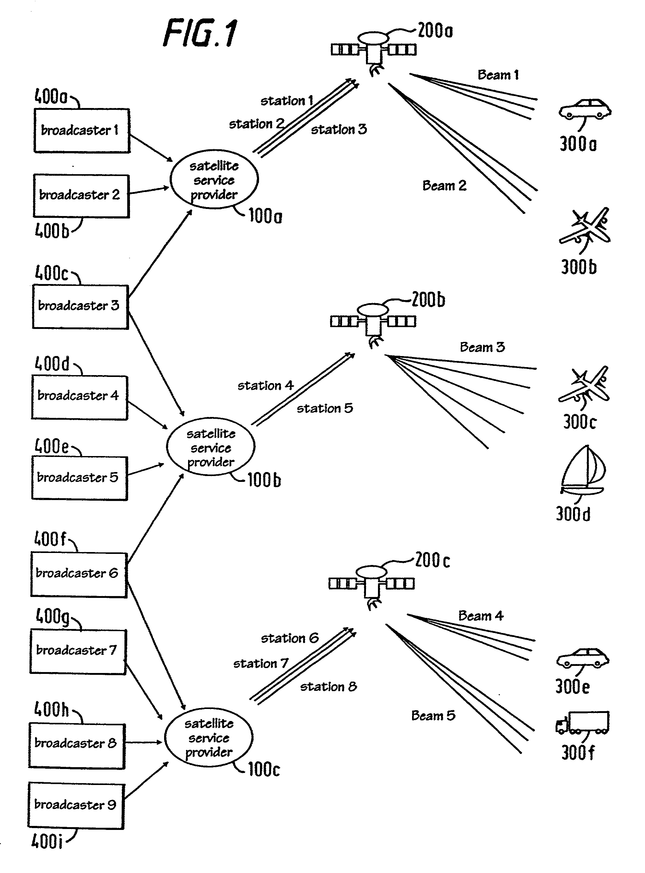
[0070] Referring to FIG. 1, the system according to the present invention comprises at least one earth station, 100a, 10b, 100c, in communication with at least one repeater satellite 200a, 200b, 200c orbiting the earth, and broadcasting to at least one receiver station 300a-300f.

[0071] The earth stations 100a-100c comprise conventional satellite tracking and RF transmission components, together with the novel circuitry described hereafter. Each earth station 100a-100c is connected to one or more broadcast data sources 400a-400i, which supply, for example, digital audio channels for broadcasting, each comprising a stream of bits carrying an audio signal.

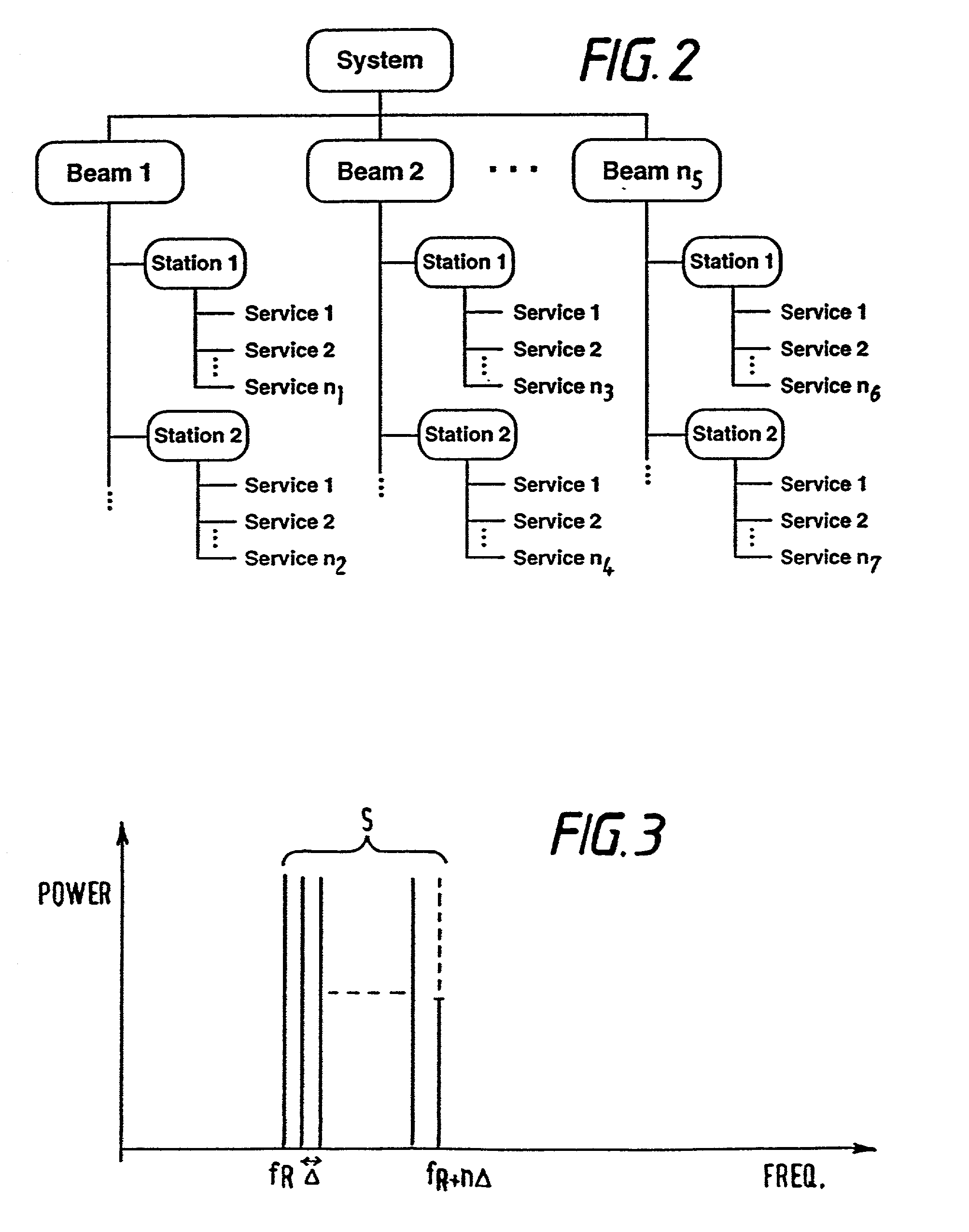
[0072] The satellites 200a-200c may be disposed in intermediate circular orbits or geostationary orbits, or in low earth orbits. Each satellite 200 is generally conventional, and operates to generate a global beam or a plurality of spot beams illuminating different regions of the earth surface beneath the satelli...


PUM


Abstract

An OFDM communications system comprises broadcast providers 400, earth stations 100, repeater satellites 200, and receivers 300 (for example mobile receivers). The size of the multiplex can be increased by adding extra channels. Two channels are provided, on the in phase and quadrature components of each subcarrier.

Description

[0001] This invention relates to apparatus and methods of frequency multiplexed communication; particularly, but not exclusively, to orthogonal frequency division multiplexing (OFDM); particularly, but not exclusively, to broadcasting using such multiplexing; particularly, but not exclusively, to broadcasting digital information.DESCRIPTION OF THE BACKGROUND ART[0002] In frequency division multiplexing, one or more information bearing signals are communicated by modulating them onto a plurality of frequency subcarriers at different frequencies. In general, the carrier frequencies are separated by an interval at least equal to the bandwidth of the information carrying signal on each carrier frequency, although in orthogonal frequency division multiplexing (OFDM) this constraint can be relaxed slightly; in OFDM, the carriers are separated in frequency by .DELTA.=1 / T, where T is the duration of each transmitted information signal, such that the centre of one band lies in the first null...

Claims


Application Information

Patent Timeline
Patent Type & Authority Applications(United States)
IPC IPC(8): H04B7/185H04H20/22H04H20/42H04H20/74H04H60/07H04L1/00H04L25/03H04L27/26
CPCH03M13/2936H03M13/6356H03M13/6362H04B7/18523H04H20/22H04H20/42H04H20/74H04H60/07H04H2201/19H04L1/0065H04L1/0069H04L1/0071H04L25/03866H04L27/2604H04L27/2623H04L27/2624
Inventor PIERZGA, WAYNE FRANCISGUINAND, PAUL SCOTTLODGE, JOHN HARRISONCROZIER, STEWART NEWMANYOUNG, RICHARD JOHN
Owner INMARSAT
Why Eureka
Try Eureka