Passenger side active knee bolster

a knee bolster and passenger technology, applied in the direction of pedestrian/occupant safety arrangement, vehicular safety arrangment, vehicle components, etc., can solve the problems of requiring a substantial amount of space within the vehicle, affecting the safety of passengers, and sacrificing occupant protection, so as to achieve substantial additional flexibility and avoid occupant protection. the effect o

Inactive Publication Date: 2002-09-12
AUTOLIV DEV AB
View PDF0 Cites 33 Cited by
  • Summary
  • Abstract
  • Description
  • Claims
  • Application Information

AI Technical Summary

Benefits of technology

0006] The present invention provides advantages and alternatives over prior knee bolster installations by providing an inflatable knee bolster which may be incorporated within an operable hinging door for a glove box disposed in opposing relation to a vehicle passenger. Heretofore, inflatable knee bolsters on a passenger side of a vehicle have been located at positions generally below the glove box in a separate installation. An independent glov

Problems solved by technology

While such a construction may provide a desired degree of protection, past constructions have been relatively complex and may require a substantial amount of space within the vehi

Method used


Image

  • Passenger side active knee bolster
  • Passenger side active knee bolster
  • Passenger side active knee bolster

Examples


Embodiment Construction

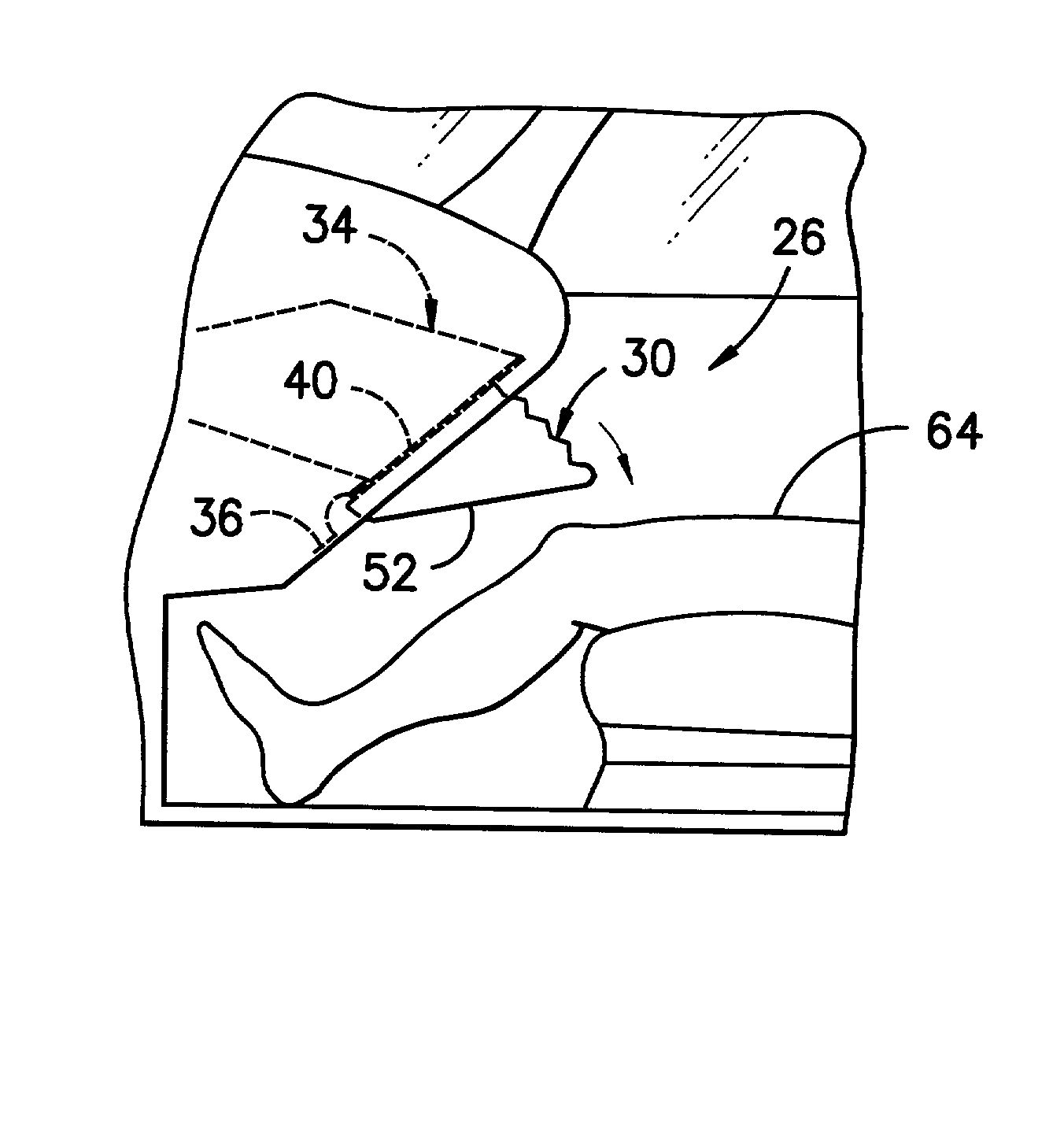
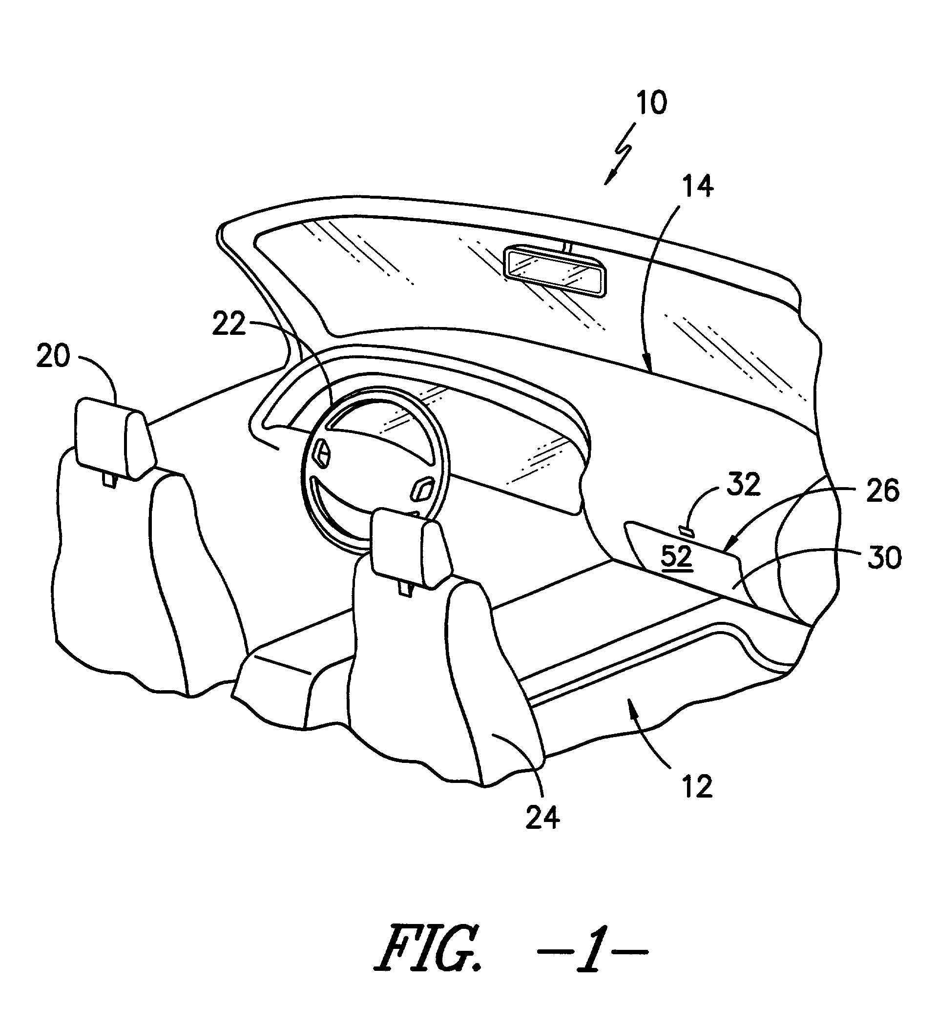
[0026] Reference will now be made the various figures wherein to the extent possible like reference numerals have been utilized to designate like components throughout the various views. In FIG. 1 a vehicle 10 such as an automotive transportation vehicle or the like is illustrated. As shown, the vehicle 10 includes an interior 12 incorporating a dash panel 14 of contoured construction. A driver side seat 20 is disposed in substantially opposing relation to a steering wheel 22 on one side of the vehicle 10. A passenger seat 24 is located on the other side of the vehicle 10 in opposing relation to a glove box 26 disposed within the dash panel 14. As shown, the glove box 26 includes a door portion 30 which may be opened by a remote latch release 32 as will be well known to those of skill in the art.

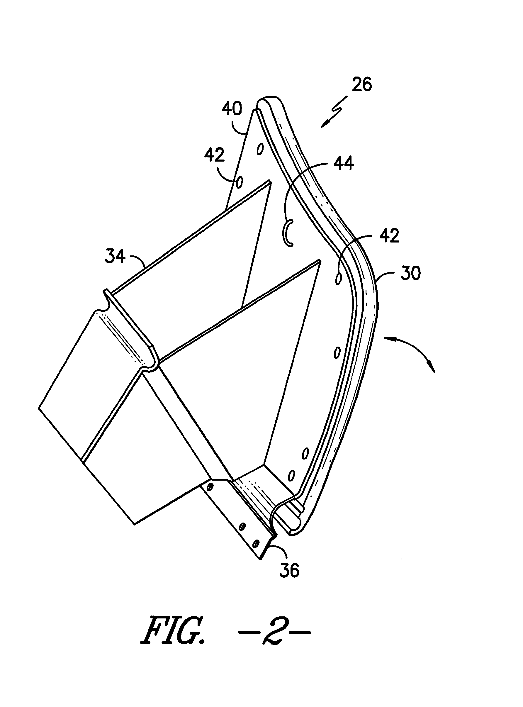
[0027] As best illustrated in FIG. 2, the glove box assembly 26 includes a door portion 30 and a bin portion 34 extending away from the door portion 30 for disposition at the interior of the...


PUM


Abstract

An automotive glove box assembly. The glove box assembly includes a storage bin and a door disposed in hinging relation to the storage bin. The door includes an expansible body having a face portion facing towards a vehicle occupant and a back portion in opposing relation to the face portion. The expansible body is operatively connected to at least one gas emitting unit such that upon discharge of gas from the gas emitting unit, the expansible body is pressurized and the face portion is projected outwardly to an extended position so as to intercept lower extremities of the occupant.

Description

CROSS-REFERENCE TO RELATED APPLICATION[0001] This is a continuation-in-part of U.S. application Ser. No. 09 / 829,445 having a filing date of Apr. 9, 2001 which is a division of application Ser. No. 09 / 479,166 filed Jan. 7, 2000 (now U.S. Pat. No. 6,213,497) which is a continuation-in-part of application Ser. No. 09 / 130,939 filed Aug. 7, 1998 (now U.S. Pat. No. 6,032,978) all of which are incorporated by reference herein.TECHNICAL FIELD[0002] This invention relates generally to inflatable vehicle protective devices and, more particularly, to an inflatable knee bolster incorporated within an operable glove box door at a passenger side of a transportation vehicle.BACKGROUND OF THE INVENTION[0003] Inflatable knee bolsters have been developed to enhance vehicle occupant protection in the event of sudden vehicle deceleration. Such devices increase the duration of deceleration of an occupant's femurs and serve to control upper torso kinematics during a frontal impact event. In operation the...

Claims


Application Information

Patent Timeline
IPC IPC(8): B60R21/045B60R21/16B60R21/20B60R21/205B60R21/215B60R21/231B60R21/233B60R21/235
CPCB60R21/045B60R21/205B60R21/206B60R21/216B60R21/2338B60R21/235B60R2021/21525B60R2021/23169B60R2021/23386B60R2021/23519
Inventor CONLEE, JAMES KENTKHOUDARI, BASSAM GEORGESWILLIAMS, CARL DENNISDAMIAN, STEVEN AUREL
Owner AUTOLIV DEV AB
Why Eureka
Try Eureka