
Picture display device of the index type

a display device and index tube technology, applied in the direction of picture reproducers, transit tubes, cathode-ray/electron beam tube circuit elements, etc., can solve the problems of limiting the performance and image quality of the index tube, both in resolution, and the small size of the electron beam perpendicular to the phosphor line, etc., to achieve the effect of improving image quality

Inactive Publication Date: 2002-09-12
KONINKLIJKE PHILIPS ELECTRONICS NV
View PDF9 Cites 2 Cited by
  • Summary
  • Abstract
  • Description
  • Claims
  • Application Information

AI Technical Summary

Benefits of technology

0005] It is an object of the invention to provide an

Problems solved by technology

The inventors have realised that one of the major problems is the required small size of the electron beam perpendicular to the phosphor lines.
If the electron beam spot size grows larger than the width of the phosphor line, it will not only hit the addressed phosphor, but also the neighbouring phosphor, which will result in a loss of colour purity.
The demands on the spot size limit the performance and image quality of the index tube, both in resolution and in brightness.

Method used


Image

  • Picture display device of the index type
  • Picture display device of the index type
  • Picture display device of the index type

Examples


Embodiment Construction

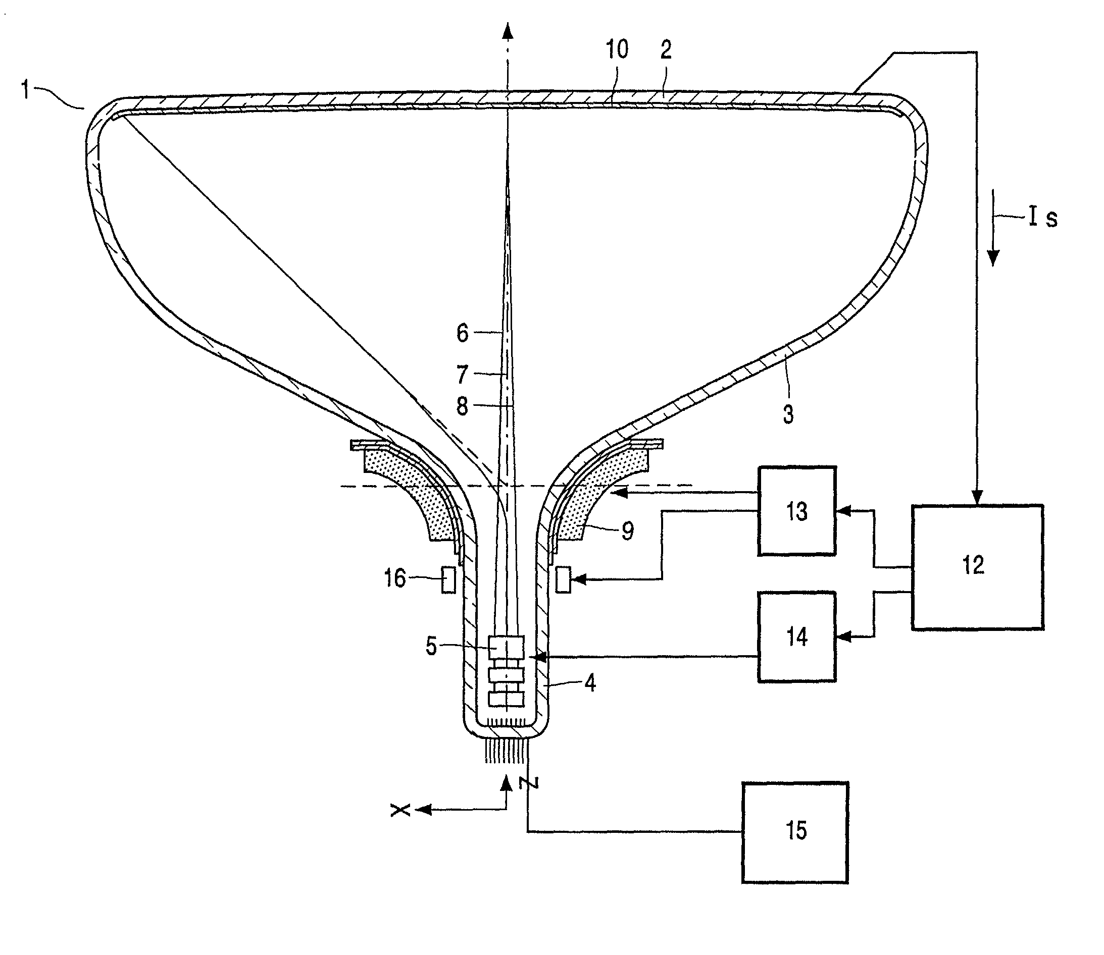
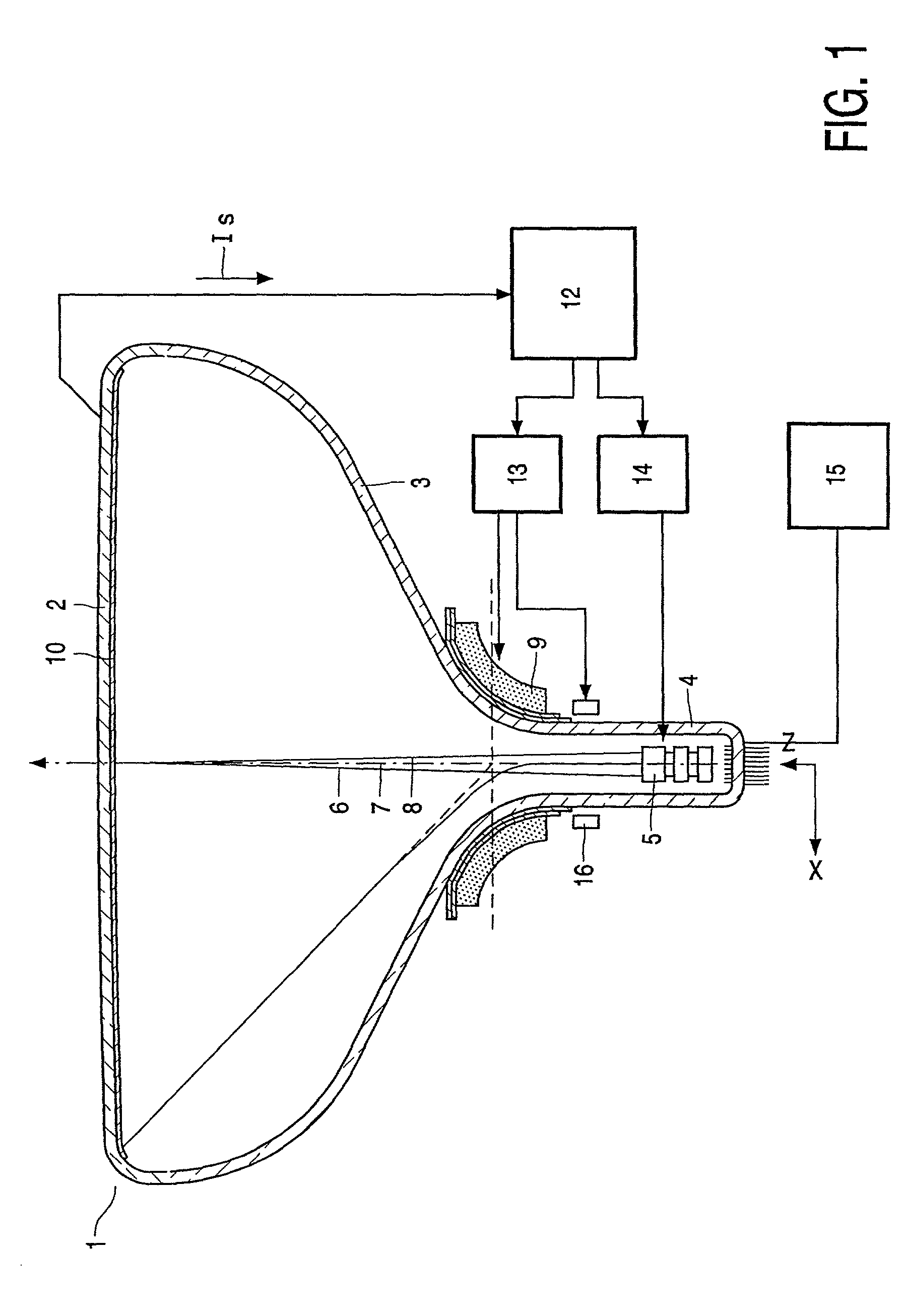
[0033] FIG. 1 shows an index display device comprising a colour cathode ray tube 1 having a display window 2, a cone 3 and a neck 4. The neck 4 accommodates an electron gun 5 for generating one or more, in this example three, electron beams 6, 7 and 8 extending, in this embodiment, in one plane, the in-line plane. A deflection system 9 is mounted on the cone 3 for deflecting the electron beams 6, 7, 8 across the display window 2. A display screen 10 is situated on the inner side of the display window 2. Said display screen 10 comprises a plurality of red, green and blue-luminescing phosphor elements. Each group of (red, green or blue) phosphor elements forms a pattern. The display screen 10 may also comprise other patterns such as a black matrix (a black pattern) or colour filter patterns.

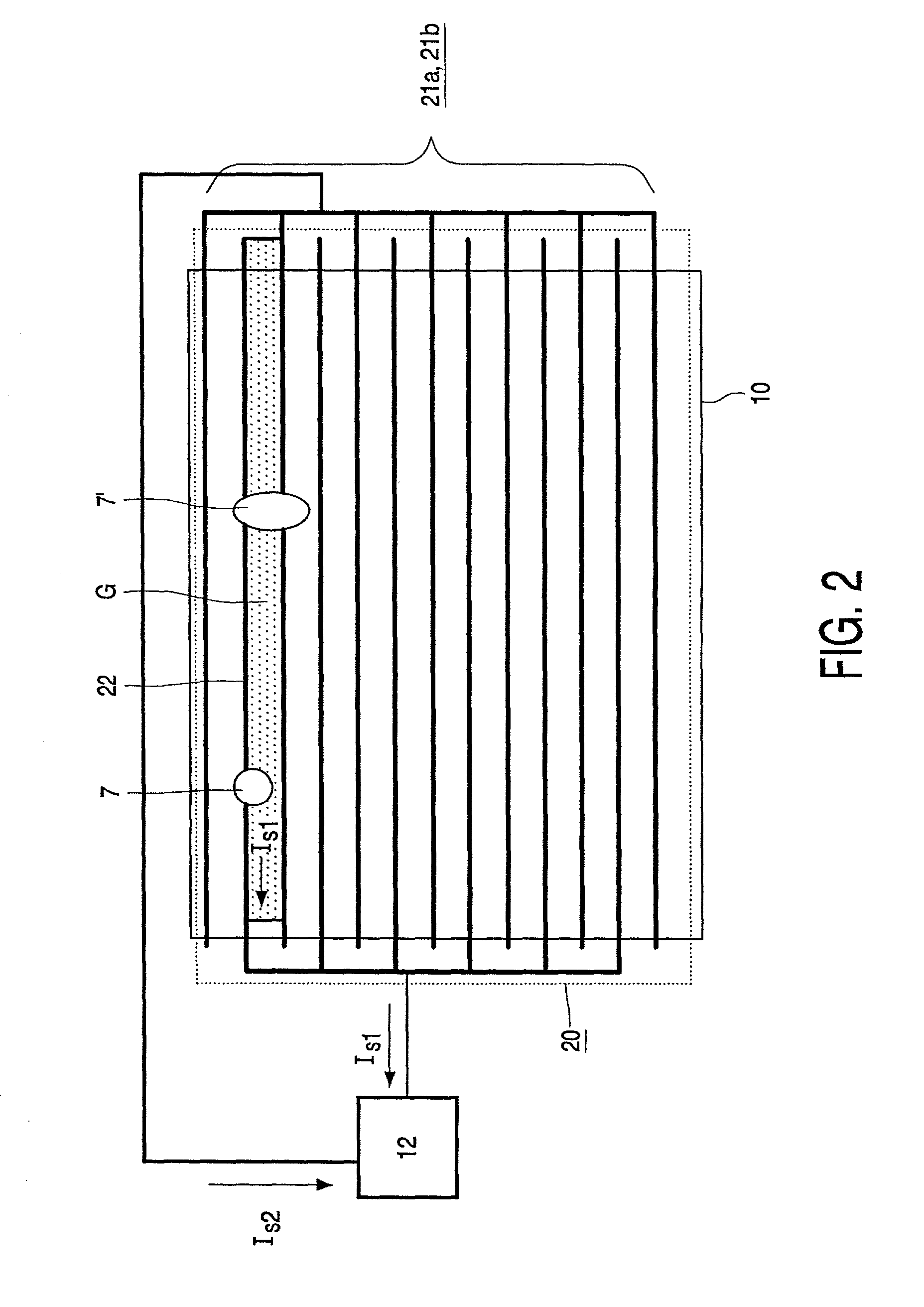
[0034] These patterns are provided with index electrodes, each index electrode comprising, in this example, a plurality of interconnected conducting elements. FIG. 2 shows a known index electrode 2...


PUM


Abstract

A picture display device of the index type comprises a cathode ray tube (1) and a display window with a display screen (10) having phosphor patterns comprising parallel aligned phosphor lines (R, G, B), and with an index system (20) having a plurality of index elements (21) extending substantially parallel to the phosphor lines. The electron beam(s) (6, 7, 8) are deflected across the display screen (10) parallel to the phosphor lines and along and across the phospor lines. The display device has no color selection electrode in front of the display screen. The phosphor lines are arranged in the color sequence A-B-C-B-A-B-C, etc., where A, B and C stand for red, green and blue phosphors or any mutation of said colors, and, in operation, the video lines overlap such that each B phosphor line is written in a single video line and each A and C phosphor line is written by two video lines.

Description

DESCRIPTION OF THE PRIOR ART[0001] The invention relates to a picture display device comprising a cathode ray tube having a means for generating at least one electron beam, a display window with a display screen having phosphor patterns comprising parallel aligned phosphor lines, said display screen being provided with an index system comprising a plurality of index elements extending substantially parallel to the phosphor lines, and a means for deflecting the at least one electron beam across the display screen parallel to the phosphor lines to scan the display screen, the display device having no colour selection electrode in front of the display screen, and the display device comprising means for imparting video information to the at least one electron beam, the image being written in a sequence of video lines.[0002] Picture display devices of the type described above are also called "index tubes" or `index` display devices.[0003] In such known index display devices, the electron...

Claims


Application Information

Patent Timeline
IPC IPC(8): H04N9/24
CPCH04N9/24H01J29/45
Inventor VAN DEN BRINK, HENDRIKUS BERNARDUSKRIJN, MARCELLINUS PETRUS CAROLUS MICHAEL
Owner KONINKLIJKE PHILIPS ELECTRONICS NV
Learn More