Wheel support bearing assembly
- Summary
- Abstract
- Description
- Claims
- Application Information
AI Technical Summary
Benefits of technology
Problems solved by technology
Method used
Image
Examples
first embodiment
[0063] [First Embodiment]
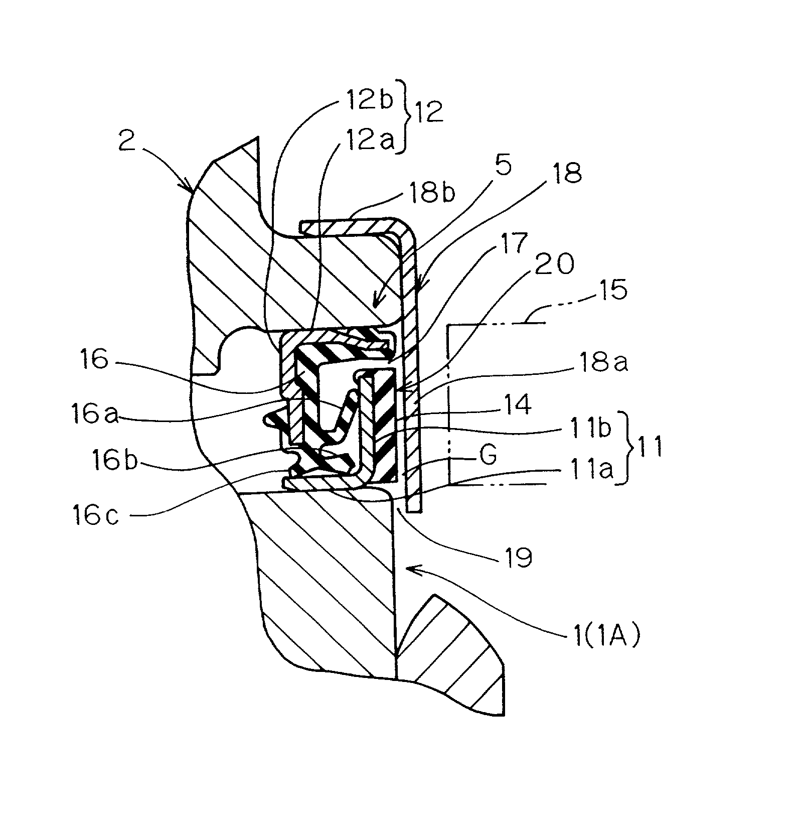
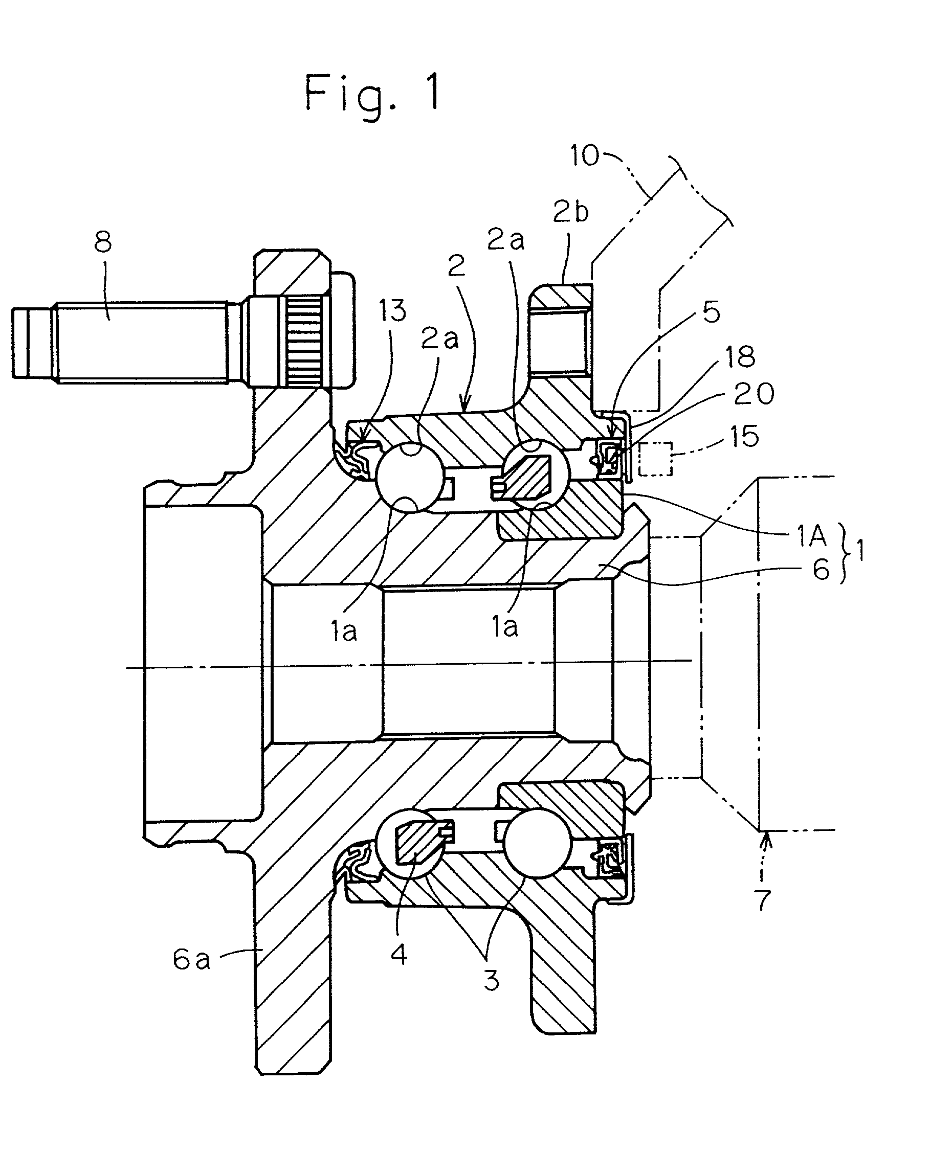
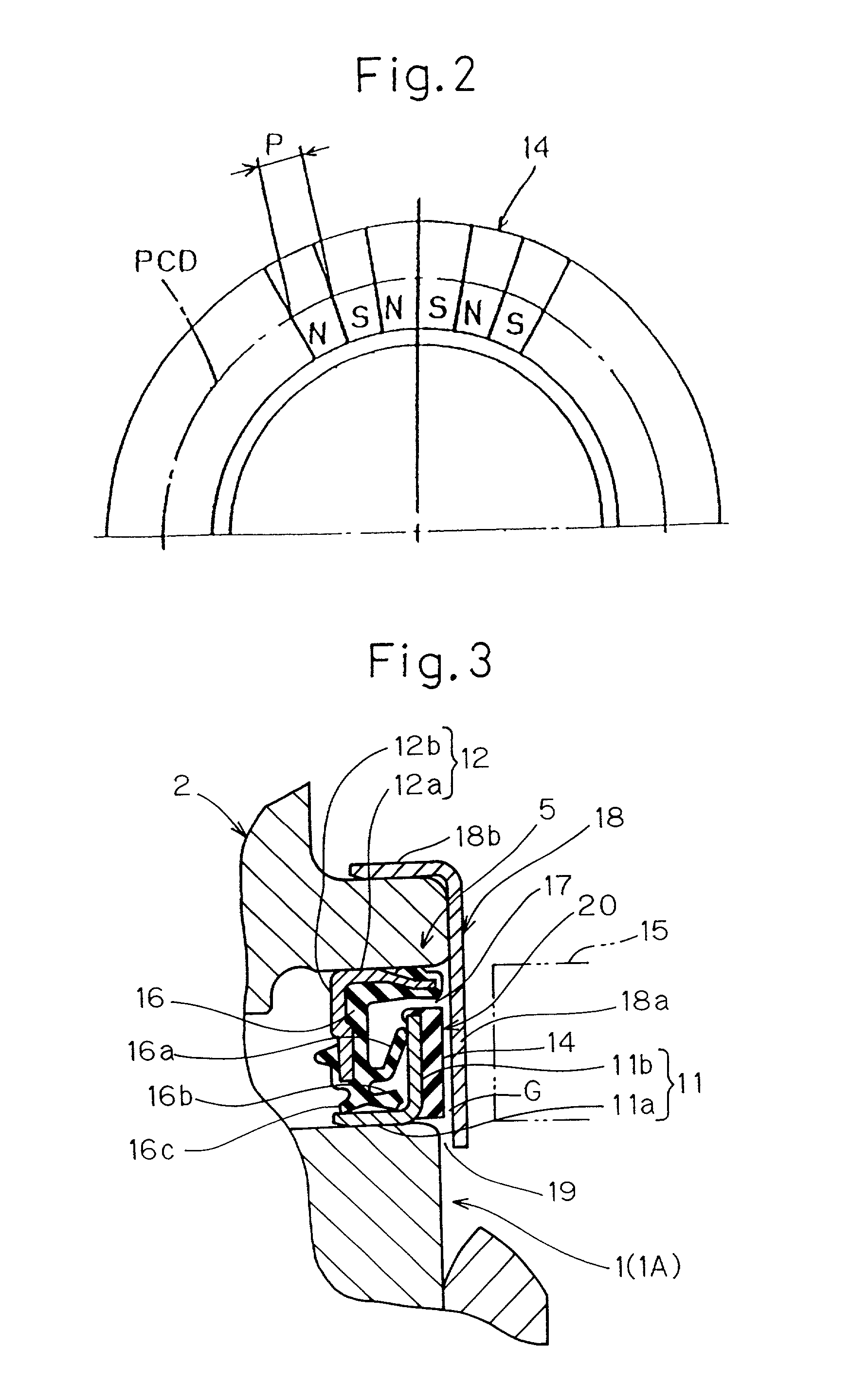
[0064] In the first place, with particular reference to FIGS. 1 to 3 showing a first preferred embodiment of the present invention, the wheel support bearing assembly shown therein will be described in the context of that used for supporting a drive wheel, in which the magnetic encoder concurrently serve as a slinger.
[0065] As shown in FIG. 1, the wheel support bearing assembly includes generally cylindrical inner and outer members 1 and 2 one positioned radially inside the other to define an annular bearing space, a plurality of, for example, two, rows of rolling elements 3 interposed between the inner and outer members 1 and 2 and rollingly movably positioned within the annular bearing space, and annular sealing devices 5 and 13 accommodated within and positioned adjacent opposite ends of the annular space, respectively, to seal the annular bearing space. It is to be noted that one of the sealing devices, that is, the sealing device 5 is provided with a ma...
second embodiment
[0090] [Second Embodiment]
[0091] The wheel support bearing assembly according to a second preferred embodiment of the present invention will now be described with reference to FIGS. 9 and 10. As is the case with the first embodiment of the present invention, the wheel support bearing assembly according to this embodiment is assumed as used for the support of the drive wheel and is thus similar in structure and function to that according to the first embodiment, except for the difference residing in that while the wheel support bearing assembly shown in FIGS. 1 to 3 employs the hub assembly of the structure including the barrel hub 6 with one of the inner race integrated therewith and the other inner race 1A, the wheel support bearing assembly reffered to as a first generation and shown in FIGS. 9 and 10 employs a three-component hub assembly of a structure including a barrel hub 6 and split-type inner races 1A and 1B. Other structural features of the wheel support bearing assembly s...
third embodiment
[0108] [Third Embodiment]
[0109] The wheel support bearing assembly according to a third preferred embodiment of the present invention will now be described with reference to FIG. 14. The wheel support bearing assembly according to this third embodiment is featured in that the protective cover 18 is fitted to the inner member 11 and that the multi-pole magnet 14 of the magnetic encoder 20 is secured to an axially inner surface of the upright wall 18b of the protective cover 18 by means of a bonding technique. Where the multi-pole magnet 14 is in the form of the rubber magnet, it may be secured by vulcanization to the upright wall 18b of the protective cover 18. A gap may or may not be formed between the radial wall 11b of the first sealing plate 11 and the multi-pole magnet 14. In such case, the multi-pole magnet 14 and the protective cover 18 altogether form the magnetic encoder 20. It is to be noted that in the embodiment shown in FIG. 14, the radial outer edge portion of the uprig...
PUM
 Abstract
Description
Claims
Application Information
 - R&D
- Intellectual Property
- Life Sciences
- Materials
- Tech Scout
- Unparalleled Data Quality
- Higher Quality Content
- 60% Fewer Hallucinations
Browse by: Latest US Patents, China's latest patents, Technical Efficacy Thesaurus, Application Domain, Technology Topic, Popular Technical Reports.
© 2025 PatSnap. All rights reserved.Legal|Privacy policy|Modern Slavery Act Transparency Statement|Sitemap|About US| Contact US: help@patsnap.com


