Fixation device for blading of a turbo-machine

Inactive Publication Date: 2002-09-12
ANSALDO ENERGIA IP UK LTD
View PDF0 Cites 19 Cited by
  • Summary
  • Abstract
  • Description
  • Claims
  • Application Information

AI Technical Summary

Benefits of technology

0009] The invention provides an intimate shape-mated connection between the wedge element and at least one immediately adjacent rotating blade, so that no relative movements between the rotating blade and t

Problems solved by technology

The risk of a complete detachment of individual rotating blades from the respective mounting means exists if the rotating blades inserted inside the mounting grooves and attached in known manners are able to move unevenly within the respective mounting play circumferentially along the mounting groove on the rotor.
Such peripheral maladjustments in a plurality of rotating blades in

Method used


Image

  • Fixation device for blading of a turbo-machine
  • Fixation device for blading of a turbo-machine
  • Fixation device for blading of a turbo-machine

Examples


Embodiment Construction

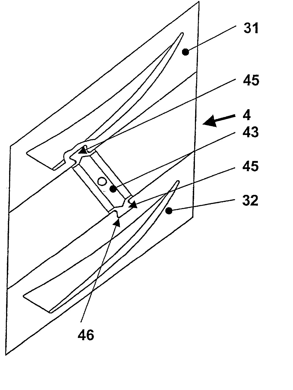
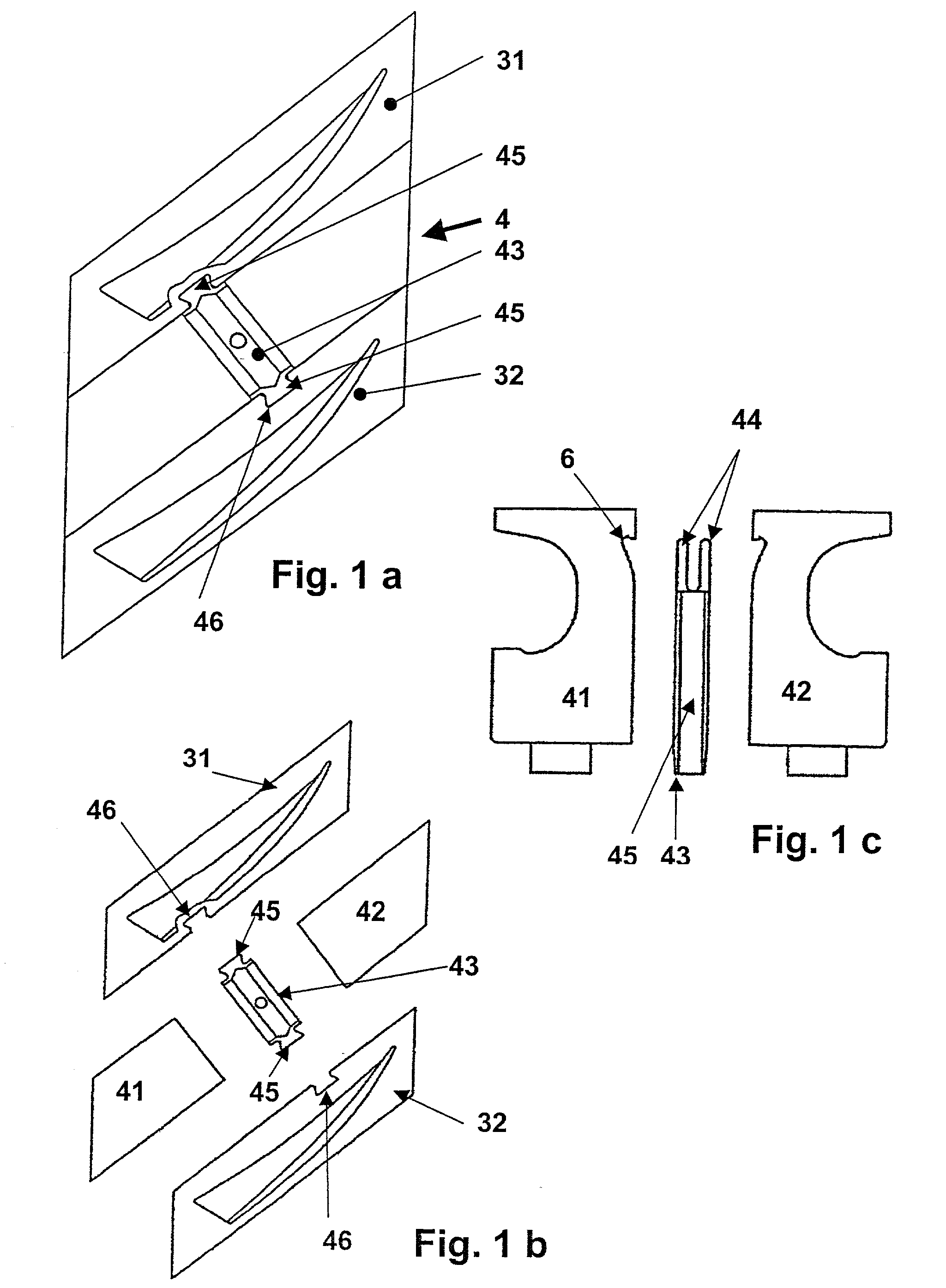
[0016] FIG. 1a shows a top view of an assembly that includes two rotating blades 31, 32 inserted within a mounting groove (not shown) and a rotor collar 4 between the rotating blades 31, 32. The rotor collar 4 has a wedge element 43 that has on its sides facing the rotating blades 31, 32 one each connecting element 45 that is constructed as a dovetail. The connecting elements each engage with a mating recess 46 worked within the rotating blades 31,32.

[0017] As a result of the mechanical connection positioned according to the invention between the rotor collar 4 and the two rotating blades 31, 32, relative movements caused by different thermal expansion phenomena can be excluded. Accordingly, no impermissible gap is able to form along the mounting groove, which gap would result in the risk of a detachment of parts located inside the mounting groove.

[0018] The individual components illustrated in the exploded view of FIG. 1b clearly show the mating recesses 46 inside the rotating blad...


PUM

PropertyMeasurementUnit
Widthaaaaaaaaaa

Abstract

A device is shown for fixing blades of a turbo-machine having a plurality of blades positioned longitudinally relative to a mounting groove. At least two blades are positioned adjacent to each other inside the mounting groove, and a mounting gap is defined between the blades. Two insertion elements constructed as collar halves can be inserted into the mounting gap, and each insertion element has a width adapted to the width of the mounting gap such that a gap space is defined between the insertion elements when they are inserted into the mounting gap. A wedge element can be inserted in the mounting gap to fix both collar halves inside the mounting groove. At least one connecting element is provided on the wedge element towards the side of a blade, and at least one of the two blades adjoining the wedge element is provided with a mating recess corresponding to the connecting element so that the wedge element and the blade are connected by a shape-mated connection.

Description

FIELD OF THE INVENTION[0001] The invention relates to a device for fixing blades in a turbo-machine. A plurality of blades is positioned longitudinally relative to a mounting groove, and between at least two blades positioned adjacent to each other inside the mounting groove, a mounting gap is provided, having two insertion elements constructed as collar halves that can be inserted into the mounting gap, and each of which has a width adapted to the width of the mounting gap and which enclose between themselves a gap space into which a wedge element can be inserted that can be wedged in such a way that both collar halves are fixed in a force-derived manner by means of the wedge element inside the mounting groove.BACKGROUND OF THE INVENTION[0002] Blades of the previously described type are related to guide blades, but in particular to rotating blades inside turbo-machines, such as, for example, the compressor or turbine stage of a gas turbine system. The following explanations relate ...

Claims


Application Information

Patent Timeline
IPC IPC(8): F01D5/30F01D5/32
CPCF01D5/3038F01D5/32F01D5/323Y10T29/49323Y10T29/37Y10T29/49321
Inventor BACHOFNER, RENEKAPPIS, WOLFGANGRIHAK, PAVELTHUERINGER, FERDINANDWALTKE, ULRICHWETTSTEIN, HANS
Owner ANSALDO ENERGIA IP UK LTD
Why Eureka
Try Eureka