Armor-Plated Machine Components and Gas Turbines

Active Publication Date: 2009-07-16
SIEMENS ENERGY GLOBAL GMBH & CO KG
View PDF5 Cites 4 Cited by
  • Summary
  • Abstract
  • Description
  • Claims
  • Application Information

AI Technical Summary

Benefits of technology

[0015]The advantages which are achieved by the invention are especially that, by means of the segmented design of the cladding of the machine component, attachment of the cladding to the base body is enabled really for the first time even in the case of only small tolerance ranges, wherein a distortion of the base body as a result of the high working temperatures during the weld surfacing can be largely avoided especially with regard to the segmented design of the cladding. By means of the segmented design of the cladding, moreover, crack formation during the application of the cladding, which could occur during continuous welding of the cladding, is avoided. Moreover, subsequent bending of the component part is enabled without the cladding material being too heavily stressed in the process. Furthermore, deformations and connecting welds during assembly and in operation are comparatively simple to carry out without fear of critical effects o

Problems solved by technology

However, during the operation of the turbine, time and again actually unwanted contact between such component parts can develop, for example as a result of thermal expansions or else as a result of operation-induced vibrations or suchlike which occur, so that certain wear of such component parts occurs.
Owing to their design, these machine components have such significant deformations and critical tolerances that during operation of the gas turbine contact between these component parts in some places is unavoidable.
As a result of this contact, unwanted and possibly also critical wear, especially during long operating periods, arises, so that the component parts which are referred to have to be inspected at regular intervals and, if necessary, exchanged/repaired.
On account of the greater hardness of the cladding material which is customary for such a

Method used


Image

  • Armor-Plated Machine Components and Gas Turbines
  • Armor-Plated Machine Components and Gas Turbines
  • Armor-Plated Machine Components and Gas Turbines

Examples


Embodiment Construction

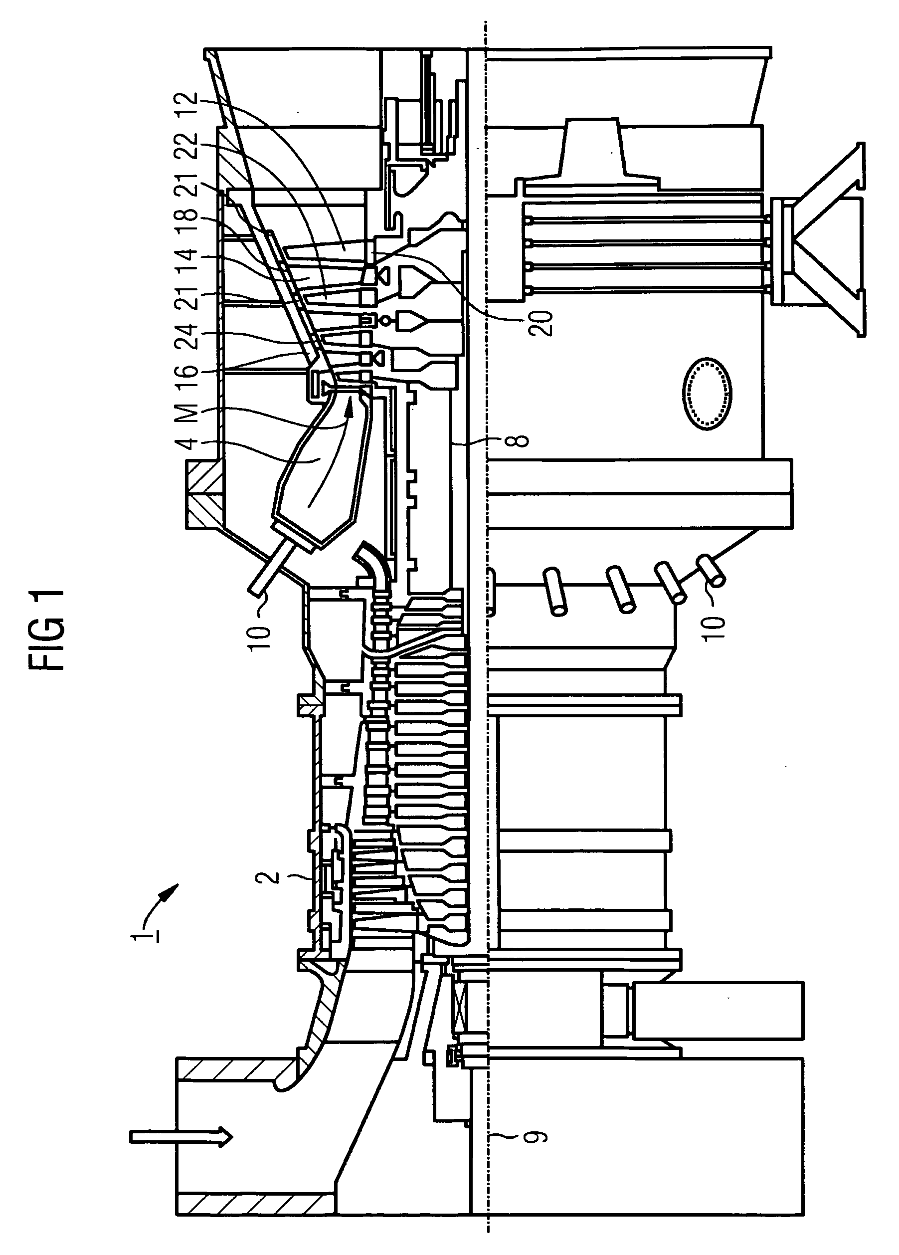
[0023]The gas turbine 1 according to FIG. 1 has a compressor 2 for combustion air, a combustion chamber 4 and also a turbine 6 for driving the compressor 2, and a generator, not shown, or a driven machine. For this purpose the turbine 6 and the compressor 2 are arranged on a common turbine shaft 8, also referred to as a turbine rotor, to which the generator or the driven machine, as the case may be, is also connected, and which is rotatably mounted around its center axis 9.

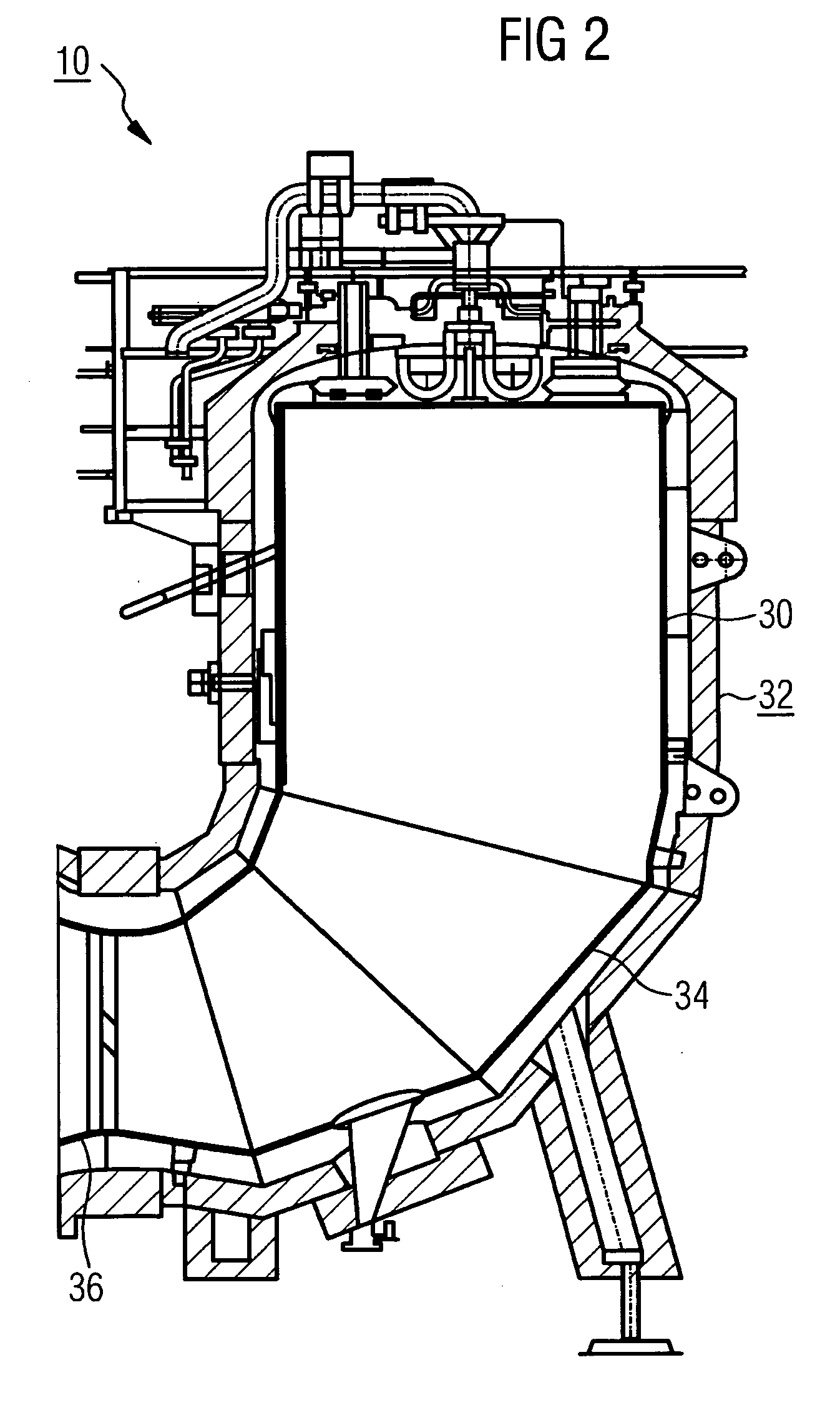
[0024]The combustion chamber 4 is equipped with a number of burners 10 for combusting a liquid or gaseous fuel. Furthermore, on its inner wall it is provided with heat shield elements, which are not shown in detail.

[0025]The turbine 6 has a number of rotor blades 12 which are rotatably connected to the turbine shaft 8. The rotor blades 12 are arranged on the turbine shaft 8 in ring form and in this way form a number of rotor blade rows. Furthermore, the turbine 6 comprises a number of stationary stator blades 14 w...


PUM

PropertyMeasurementUnit
Hardnessaaaaaaaaaa

Abstract

The invention relates to a machine component with a base made of a base material, a part of the surface of which has been equipped with armor-plating, made of a plating material with greater hardness in comparison to the base material, with the armor-plating being segmented and made up of a number of armor-plating segments.

Description

CROSS REFERENCE TO RELATED APPLICATIONS[0001]This application is the U.S. National Stage of International Application No. PCT / EP2007 / 054029, filed Apr. 25, 2007 and claims the benefit thereof. The International Application claims the benefits of European application No. 06011629.0 filed Jun. 6, 2006, both of the applications are incorporated by reference herein in their entirety.FIELD OF INVENTION[0002]The invention relates to a machine component with a base body which is manufactured from a base material and which in a section of its surface is provided with a cladding consisting of a cladding material with a greater hardness in comparison to the base material. Furthermore, it relates to a gas turbine with a number of machine components of this type.BACKGROUND OF THE INVENTION[0003]Turbines, especially gas turbines, are used in many areas for driving generators or driven machines. In this case, the energy content of a fuel is used to produce a rotational movement of a turbine shaft...

Claims


Application Information

Patent Timeline
IPC IPC(8): F01D5/28
CPCC23C30/00F23R3/005F23R3/002F23M2900/05001
Inventor GRUGER, BIRGITSTAPPER, MARTIN
Owner SIEMENS ENERGY GLOBAL GMBH & CO KG
Why Eureka
Try Eureka