Gas chromatograph injection valve

a technology of gas chromatograph and injection valve, which is applied in the direction of chemical/physical processes, disinfection, sulfur-dioxide/sulfurous acid, etc., can solve the problems of the size of the valve apparatus, the microvalves of the reference do not provide sample depressurization, and the quality of the sample analysis

Inactive Publication Date: 2002-09-12
SYMYX TECHNOLOGIES +1
View PDF15 Cites 33 Cited by
  • Summary
  • Abstract
  • Description
  • Claims
  • Application Information

AI Technical Summary

Benefits of technology

0009] Among the several objects and features of the present invention may be noted the provision of a gas injection valve comprising one or more microvalves; the provision of such an injection valve wherein each microvalve is capable of being independently actuated; the provision of such an injection valve that may be micro-fabricated;

Problems solved by technology

Injecting samples into a carrier stream at a different pressure is undesirable as pressure gradients can cause sample dispersion, which results in unwanted band broadening that may detrimentally affect the quality of the analysis of the sample.
Thus, the microvalves of the reference do not

Method used


Image

  • Gas chromatograph injection valve
  • Gas chromatograph injection valve
  • Gas chromatograph injection valve

Examples


first embodiment

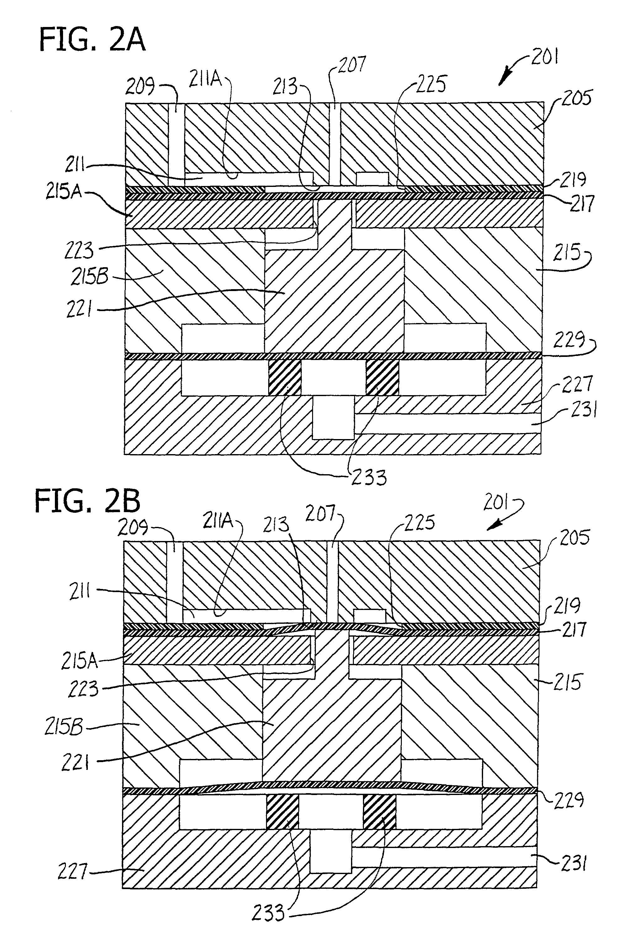
[0038] Referring to FIGS. 2A and 2B, in a first embodiment, an injection valve 201 of the present invention comprises a single microvalve. It is important to note that the injection valve of the present invention includes a top plate (not shown in the schematic diagrams of FIGS. 2A and 2B) that will be fully described herein in relation to FIG. 5.

[0039] Referring back to FIGS. 2A and 2B, microvalve 201 generally comprises a first plate 205 having an inlet passage 207, an outlet passage 209 and a fluid transfer channel 211. The inlet passage 207 and outlet passage 209 extend through the first plate 205 from a first face to a second face. The fluid transfer channel 211 formed in the first face of the first plate 205 has a floor 211A and extends between the inlet passage 207 and outlet passage 209 of the first plate 205 for fluid communication therebetween.

[0040] The microvalve 203 further comprises a valve seat 213, a second plate 215, a sealing membrane 217, a spacer membrane 219 and...

fourth embodiment

[0067] In a fourth embodiment, the injection valves of the present invention are arranged in a parallel array of injection valves capable of controlling fluids from multiple sources substantially simultaneously. The parallel injection valve array may be built up from plural independent injection valve modules (e.g., as shown in FIG. 8A) or formed in a unitary body. For example, the parallel injection valve array may typically comprise a plurality of independent injection valve modules substantially similar to the injection valve 401 described above in relation to the third, preferred embodiment of the invention and illustrated in FIG. 4. Referring now to FIG. 8A, such a typical independent injection valve module generally comprises a valve body 503 including a sample gas inlet passage 505 adapted for connection to a line for receiving gas at different pressures, a gas outlet passage 507, and a gas sample loop 509.

[0068] Referring now to FIGS. 8B through 8D, a parallel injection valv...

third embodiment

[0069] In a particularly preferred parallel array, the injection valves 501 are substantially similar to those described above in the present invention. Thus, each injection valve of the parallel array is constructed and arranged for segregating fluid received into discrete samples, and to depressurize any sample having a pressure in excess of a predetermined maximum whereby samples leaving the injection valve array are of similar pressures. Further, each injection valve of the array comprises plural microvalves with at least some of the microvalves within each injection valve being independently operable from each other. Also, the injection valve array may be preferably configured with at least some of the injection valves interconnected for simultaneous actuation.

[0070] Referring now to FIG. 8B, a particularly preferred parallel array of the present invention generally comprises a plurality of individual injection valve bodies 503, each of which include a sample gas inlet passage ...


PUM

PropertyMeasurementUnit
Pressureaaaaaaaaaa

Abstract

A novel gas injection valve for injecting discrete charges of gas into a mobile phase or carrier stream is provided. Injection valves of the invention comprise a plurality of microvalves capable of receiving gas at different pressures and emitting discrete charges of gas at approximately the same pressure. The invention further provides for parallel injection valve arrays capable of injecting multiple samples substantially simultaneously and a method of injecting discrete gas samples at a controlled pressure to a high-resolution gas chromatograph.

Description

CROSS-REFERENCE TO RELATED APPLICATIONS[0001] This application claims priority from U.S. Provisional Patent Application Serial No. 60 / 274,022, filed Mar. 7, 2001. The entire text of U.S. Provisional Application Serial No. 60 / 274,022 is hereby incorporated herein by reference.BACKGROUND OF THE INVENTION[0002] The present invention generally relates to a novel fluid control valve, more particularly an injection valve comprising a plurality of microvalves for injecting discrete charges of gas into a mobile phase or carrier stream, which is particularly useful in high resolution gas chromatography. Further, the present invention provides for parallel arrays of gas injection valves in which multiple samples may be injected into multiple carrier streams substantially simultaneously.[0003] The parallel injection valves of the present invention can be advantageously incorporated into parallel detection systems, including especially parallel gas chromatographs.[0004] In a preferred applicati...

Claims


Application Information

Patent Timeline
IPC IPC(8): F15C5/00F16K7/14F16K27/00F16K99/00G01N30/20
CPCF16K2099/0084G01N30/20G01N2030/205F15C5/00F16K7/14F16K27/003F16K99/0001F16K99/0015F16K99/0059F16K2099/0076F16K2099/008Y10T436/2575
Inventor BERGH, H. SAMPINKAS, DANIEL M.
Owner SYMYX TECHNOLOGIES
Why Eureka
Try Eureka