Network node apparatus, network system using the same and fault location detecting method

Inactive Publication Date: 2002-09-12
NEC CORP
View PDF8 Cites 107 Cited by
  • Summary
  • Abstract
  • Description
  • Claims
  • Application Information

AI Technical Summary

Benefits of technology

0013] Thus, the present invention has been achieved to solve the aforementioned problems associated with the prior art, and it is an object of the invention to provide a network node apparatus that

Problems solved by technology

However, there is a problem with the transparent optical network as shown in FIG. 27, that it is not easy to identify the interval of the optical path in which the fault has occurred because only the electrical termination sets 34a and 34b within the client devices 33a and 33b at both ends of the optical path can detect the fault information.
However, with the above technique in which an optical/electrical converter having the same bit rate of the principal signal is required in each network node apparatus, there is a problem that a feature of a transpar

Method used


Image

  • Network node apparatus, network system using the same and fault location detecting method
  • Network node apparatus, network system using the same and fault location detecting method
  • Network node apparatus, network system using the same and fault location detecting method

Examples


Embodiment Construction

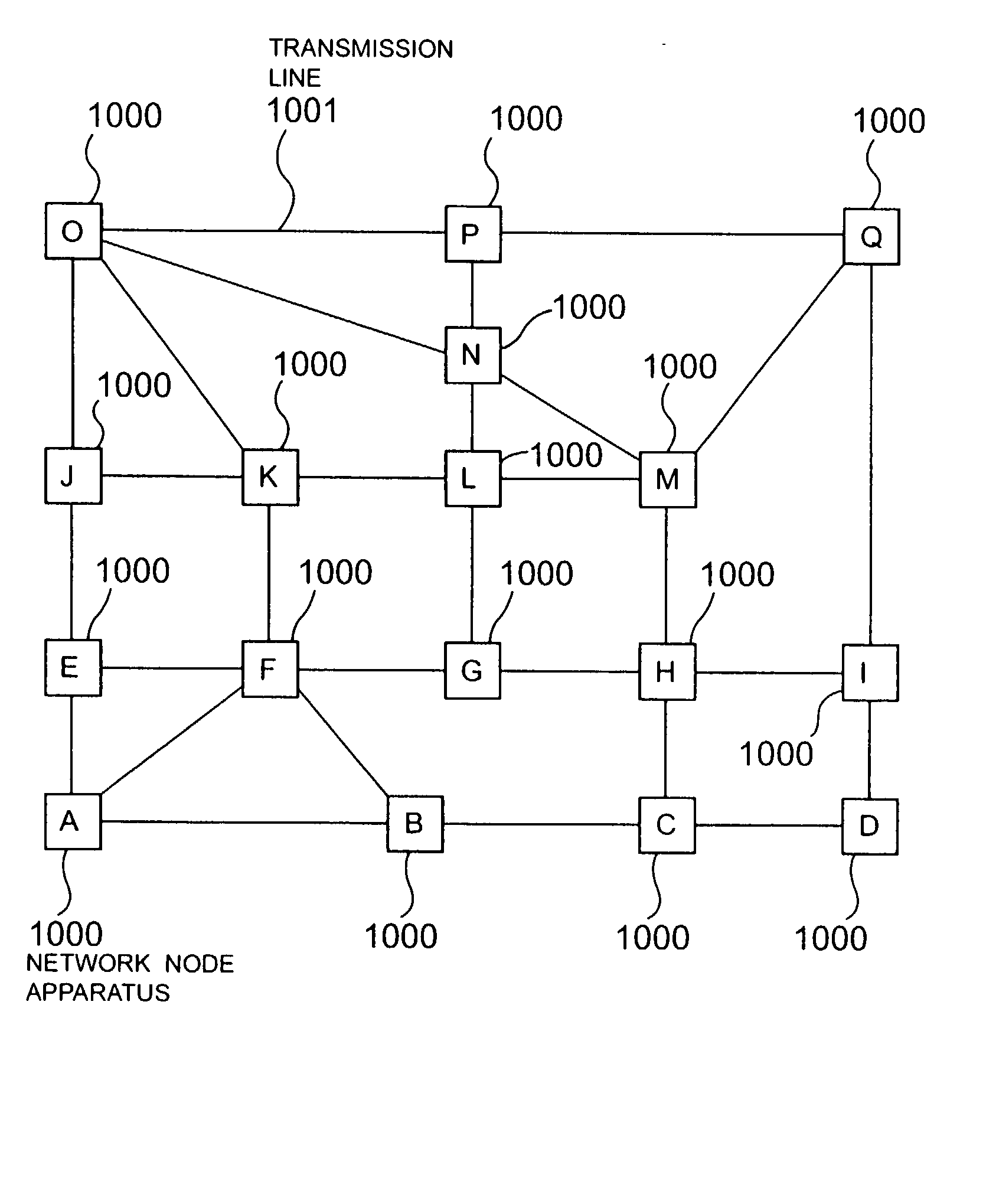
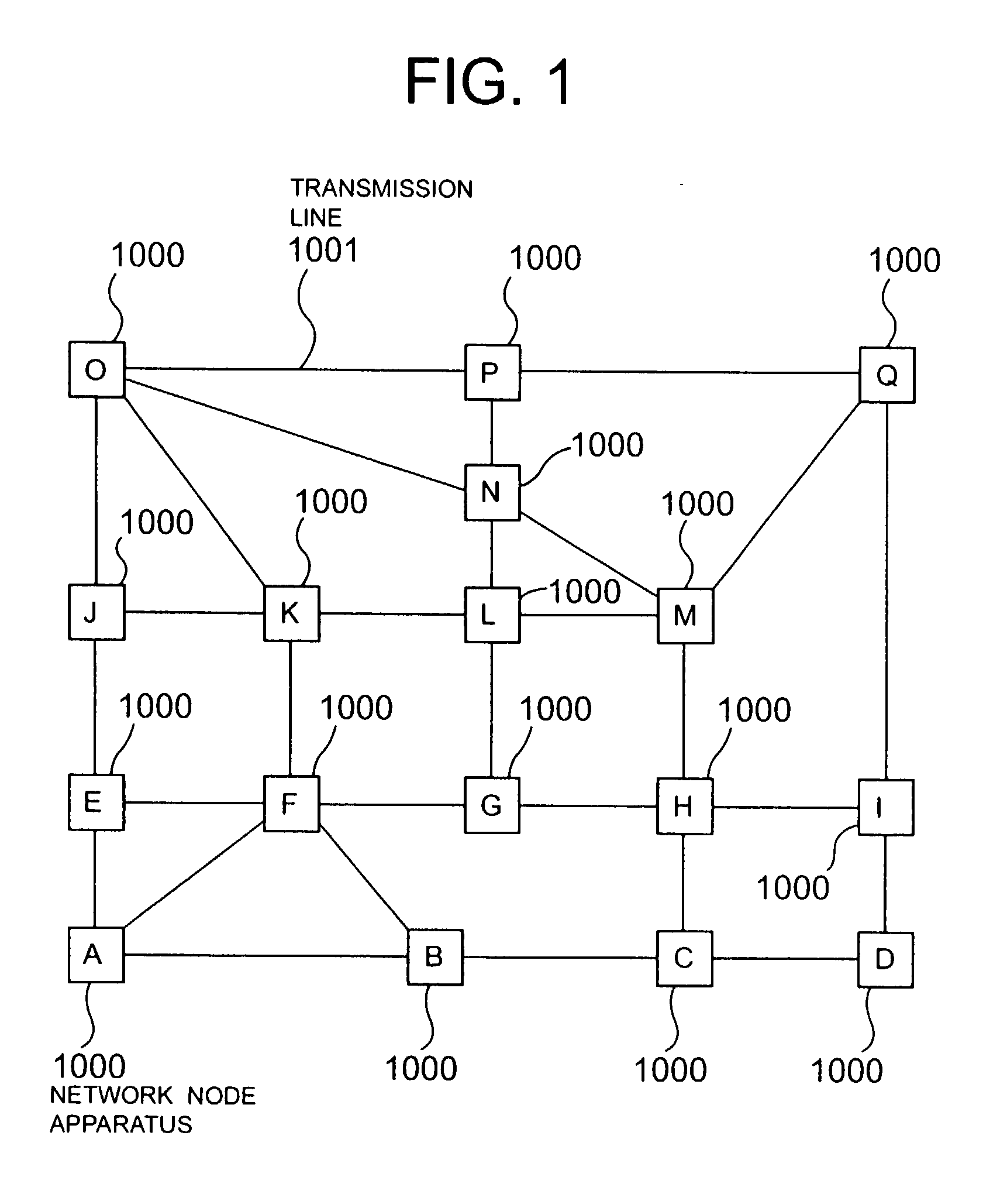
[0064] The preferred embodiments of the present invention will be described below with reference to the accompanying drawings. FIG. 1 is a diagram showing the configuration of an entire network according to an embodiment of the invention. In FIG. 1, reference numeral 1000 denotes each network node apparatus, an input terminal and an output terminal of each of a plurality of network node apparatuses A to Q being connected to respective ones of a plurality of transmission lines 1001.

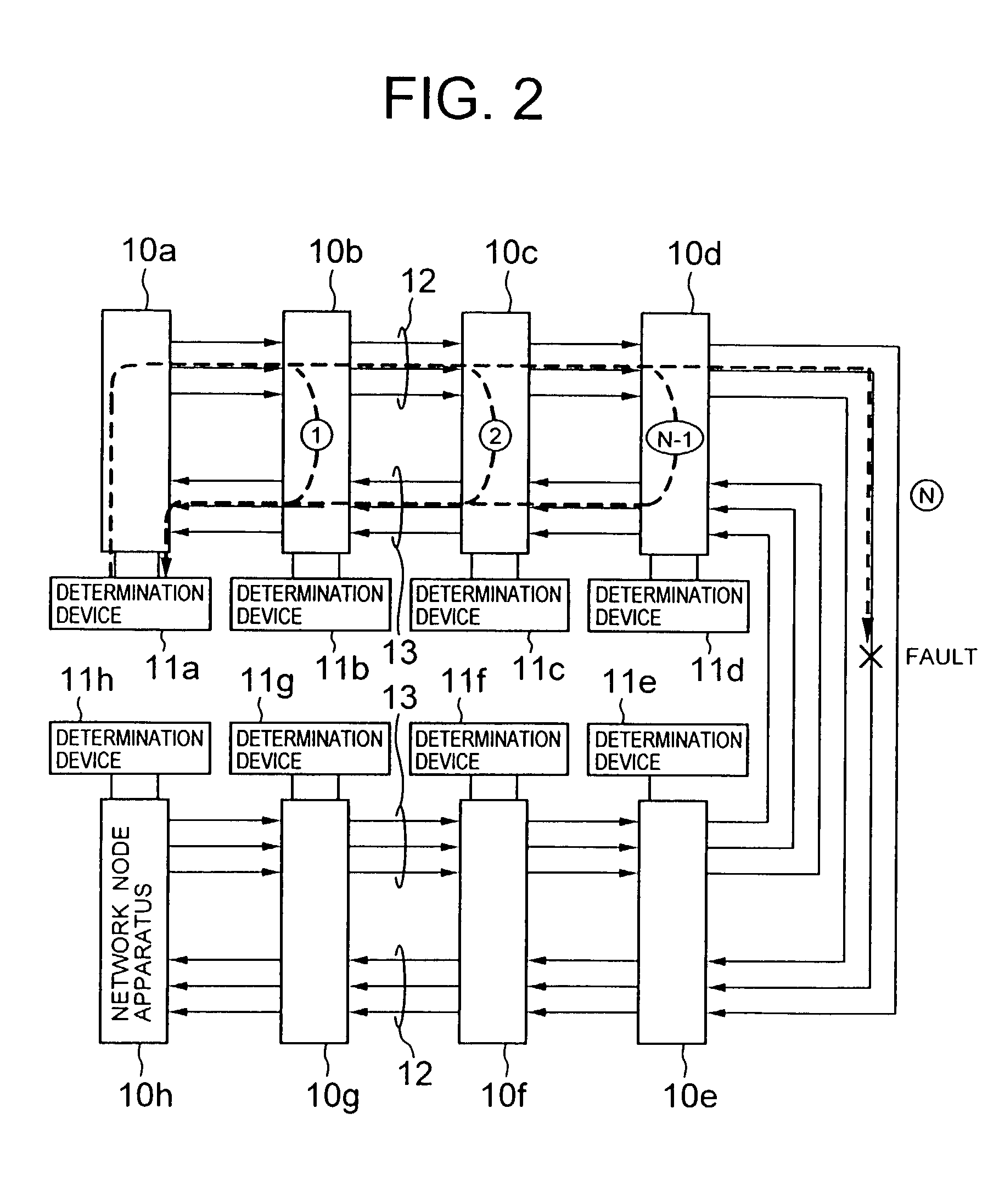
[0065] The network comprising a plurality of network node apparatuses will be described below. FIG. 2 is a block diagram showing the configuration of the network comprising the plurality of network node apparatuses, and showing a part of the entire network of FIG. 1. In FIG. 2, the network of the invention is composed of the transparent network node apparatuses 10a to 10h on an optical path for the working system (current optical path), the determination devices 11a to 11h, and a plurality of transmission ...


PUM


Abstract

To identify a fault location easily if there is any fault detected in a network. If an optical path is switched from a working system to an auxiliary system due to a fault, an optical test signal originated from a network node apparatus located at an end point of the optical path is looped back by another network node apparatus on the optical path for the working system. This looped back optical signal is received by the network node apparatus of an originator, in which the signal quality of the optical test signal is measured by a determination device, thereby detecting the presence or absence of the fault on the path through which the optical test signal has been passed. A test receiver within the determination device measures a BER, an S/N ratio, an optical power, or an optical wavelength, whereby it is possible to detect not only the fault location due to disconnection of a link but also degradation in the signal quality.

Description

BACKGROUND OF THE INVENTION[0001] 1. Field of the Invention[0002] The present invention relates to a network node apparatus, a network system using the network node apparatus, and its fault location detecting method, and more particularly to a network node apparatus having an input terminal and an output terminal being to connected to a transmission line, which forms a bi-directional transmission path via the transmission line to the other network node apparatus, a network system using the network node apparatus, and its fault location detecting method.[0003] 2. Description of the Related Art[0004] Conventionally, a network fault is detected for each link between adjacent network node apparatuses, and recovered for each link. For example, a network configuration of a path route switching system as disclosed in Japanese Patent Laid-Open No. 8-130523 is shown in FIG. 26. In FIG. 26, reference numerals 35a to 35e denote network node apparatuses, reference numerals 30a to 30h denote ele...

Claims


Application Information

Patent Timeline
IPC IPC(8): H04B10/03H04B10/035H04B10/07H04B10/077H04B17/00H04L1/22H04L12/26
CPCH04B10/035H04B10/07H04B10/0771H04B10/0775
Inventor NISHIOKA, ITARUSUEMURA, YOSHIHIKOIWATA, ATSUSHI
Owner NEC CORP
Why Eureka
Try Eureka