

Small footprint direct drive mechanical positioning stage
- Summary
- Abstract
- Description
- Claims
- Application Information
AI Technical Summary
Benefits of technology
Problems solved by technology
Method used
Image

Examples
Embodiment Construction
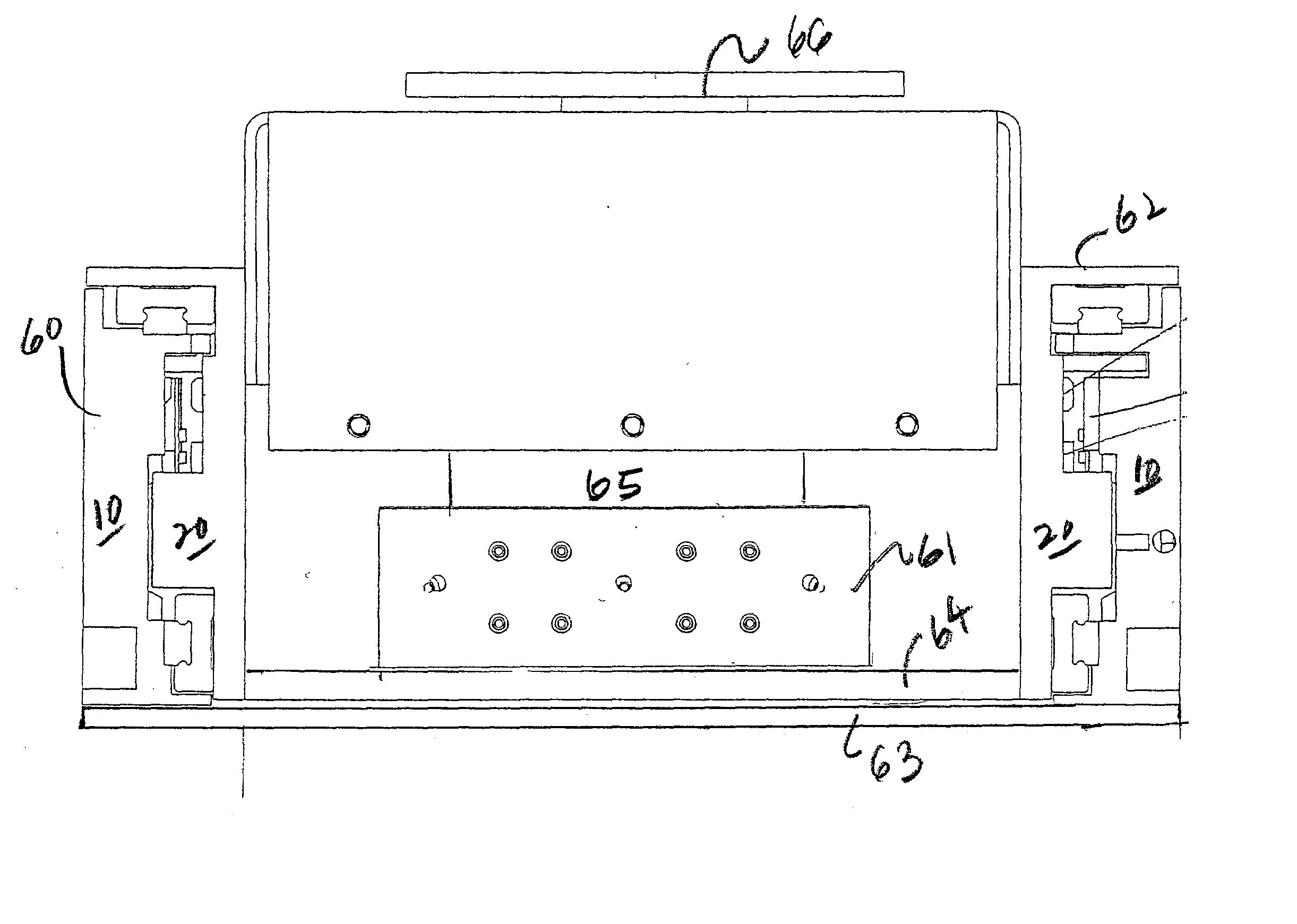
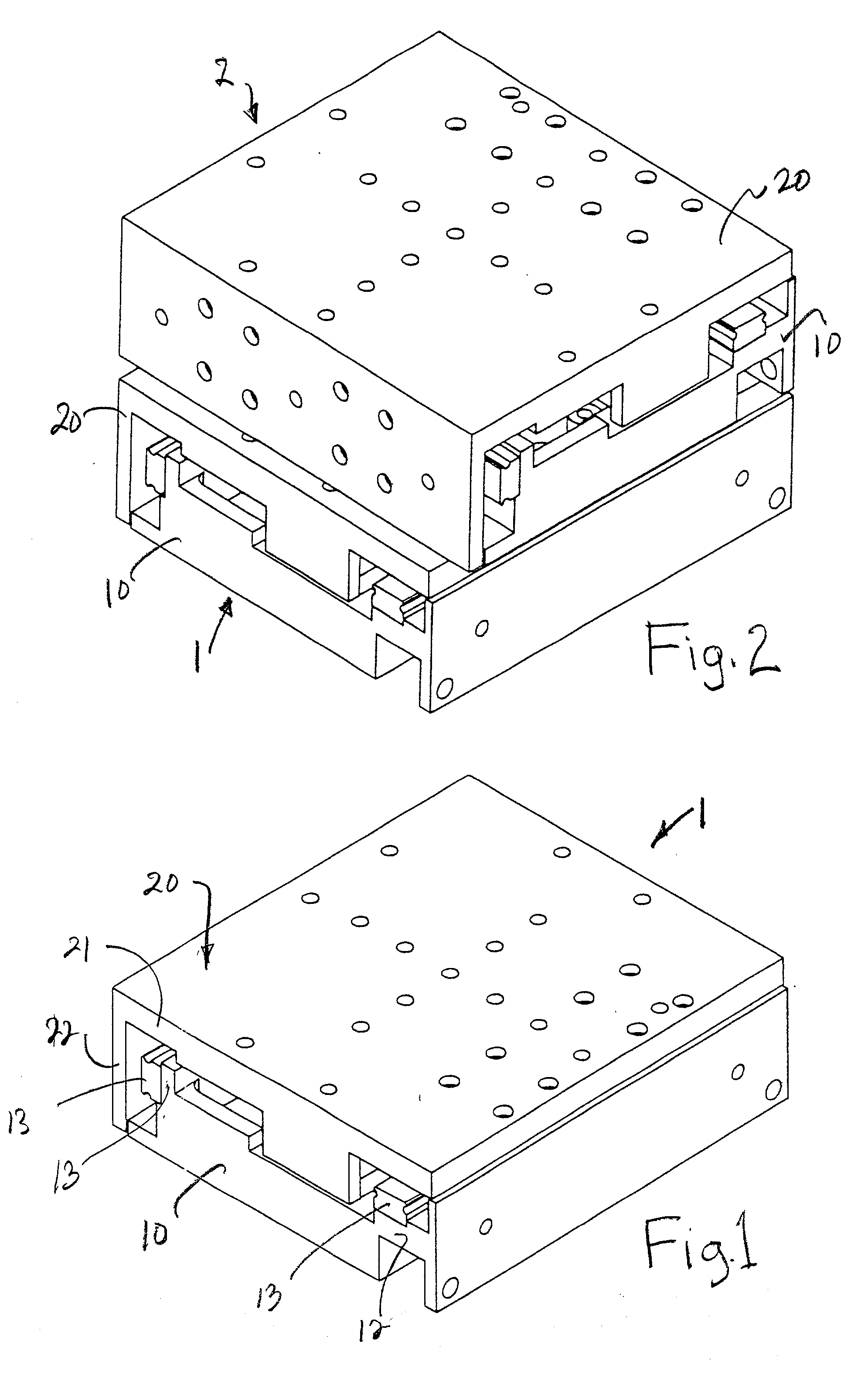
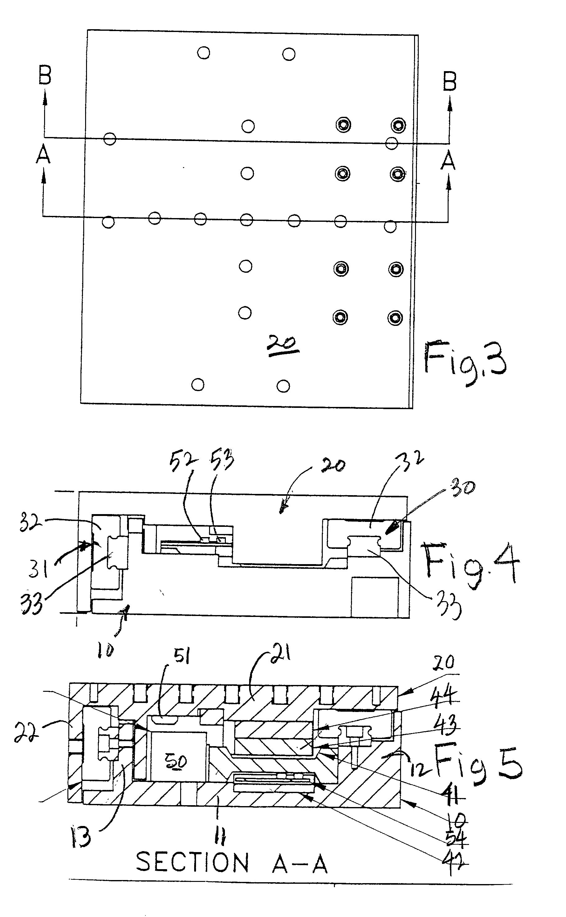
[0024] Referring now to FIG. 1, there is shown a perspective view of a small footprint mechanical positioning stage. The stage is comprised of a base plate 10 having a flat bed 11 (see FIGS. 4, 5 and 6) having two substantially parallel edges, a short raised platform 12 near one of the parallel edges of the flat bed 11, and a wall 13 spaced a short distance from the opposite edge of the flat bed 11 perpendicular thereto. Typically, the base plate 10 is machined from aluminum and aluminum alloys which are nonmagnetic and one-third as heavy as steel. The lighter weight reduces the inertia to be overcome by the linear motor. The positioning stage has a carriage plate 20 comprised of a table plate 21 and a perpendicular pendent side wall 22. Typically, the carriage plate 20 is machined from aluminum and aluminum alloys. The footprint of the positioning stage has been successfully reduced to 90.times.100 mm (3.542.times.3.937 inches). The total height of the stage is about 33 mm (1.299 i...
PUM
| Property | Measurement | Unit |
|---|---|---|
| Length | aaaaa | aaaaa |
| Length | aaaaa | aaaaa |
| Length | aaaaa | aaaaa |
Abstract
Description
Claims
Application Information