Touch Entry Display Mount

a display mount and touch technology, applied in the field of display mounts, can solve the problems of reducing rigidity of slides, poor stability of slide mounts when extended, and reducing the efficiency of supporting the weight of some monitors, so as to reduce the vertical height, reduce the twisting of hangers, and maximize strength

Active Publication Date: 2015-04-23
RUSS BASSETT
View PDF19 Cites 1 Cited by
  • Summary
  • Abstract
  • Description
  • Claims
  • Application Information

AI Technical Summary

Benefits of technology

[0013]In accordance with another aspect of the invention, there is provided a TED mount having a triangular shaped hanger to act as a gusset, maximizing strength at the TED mount while minimizing the vertical height at the front where the equipment boxes are pivoting.
[0014]In accordance with yet another aspect of the invention, there is provided a TED mount having a hanger and carrier including reliefs cut into the hanger and carrier above and below the axles. The reliefs allow the interior dimensions of the hanger and carrier to be somewhat greater than the axle sleeves while allowing axle attachment portions of the hanger and carries to be compressed against the sleeves when the axle bolts are tightened—eliminating the twisting of the hanger and carrier which would otherwise occur.
[0015]In accordance with another aspect of the invention, there is provided a TED mount having rotating cable ties. The rotating ties allow cables to rotate when the carrier is moved to reduce stress on the cables.
[0016]In accordance with another aspect of the invention, there is provided a slatwall hanger which eliminate stress created by known clamp on hangers. The slat wall hanger includes opposing inner and outer lips which sandwich vertical faces of the slats and do not apply vertical forces to the slats. The inner lips are inserted between the vertical slat members and dropped into position behind the vertical slat members. The inner and outer lips are then drawn together to horizontally sandwich the vertical slat members, applying no vertical clamping force on the slats. Such sandwiching the vertical slat members eliminates of the stress on the slat that's associated with the known clamping action. As a result, the slats can carry more weight without making the slats physically larger to increase strength, with a resulting loss in the number of hangers which may be attached to the slatwall.
[0017]In accordance with another aspect of the invention, there is provided a slatwall hanger which sandwiches the vertical slat members between inner and outer lips rather than grasping vertically spaced apart slats. Rubber bumpers and / or rubber stick-on pads are attached to the outer lips to protect vertical faces of the slats from scratches.
[0018]In accordance with still another aspect of the invention, there is provided a slatwall hanger having inner and out lips biased apart. In order to engage the slatwall, the inner lip has to be pushed inward between adjacent slats. The larger the slatwall hanger, the more difficult this installation method is. To improve the ease of installation, a spring is incorporated biasing the inner and outer lips apart, making it easier to engage the slatwall hanger with the slatwall. After positioning the slatwall hanger on the slatwall, the lips are drawn together using screw, levers, or other mechanical apparatus.

Problems solved by technology

Unfortunately, parallel horizontal arms cannot efficiently support the weight of some monitors.
At full extension such slides have reduced rigidity and may bind or fail.
The two slides on a carriage may feel reasonably stable in the closed position, but as the slides approach the extended position there is excessive lateral instability and there is nothing forcing the slides to extend synchronously, and a slide mount which requires a short compressed length has poor stability when extended.
While this provides an effective method of securing the hanger, because the vertically opposed clamps are drawn together, the amount of vertical force exerted on the slats may be excessive, causing stress on a horizontal portion of the slat, and sometimes breaking the slat even before any load is applied by the hanger.
With very heavy loads and long lever arms, the stress on the slat can be excessive.
Because installations may require a large number of hangers, clamps and clips to be attached to the slatwall, the horizontal portion of the slats can not be made thicker.

Method used


Image

  • Touch Entry Display Mount
  • Touch Entry Display Mount
  • Touch Entry Display Mount

Examples


Embodiment Construction

[0072]The following description is of the best mode presently contemplated for carrying out the invention. This description is not to be taken in a limiting sense, but is made merely for the purpose of describing one or more preferred embodiments of the invention. The scope of the invention should be determined with reference to the claims.

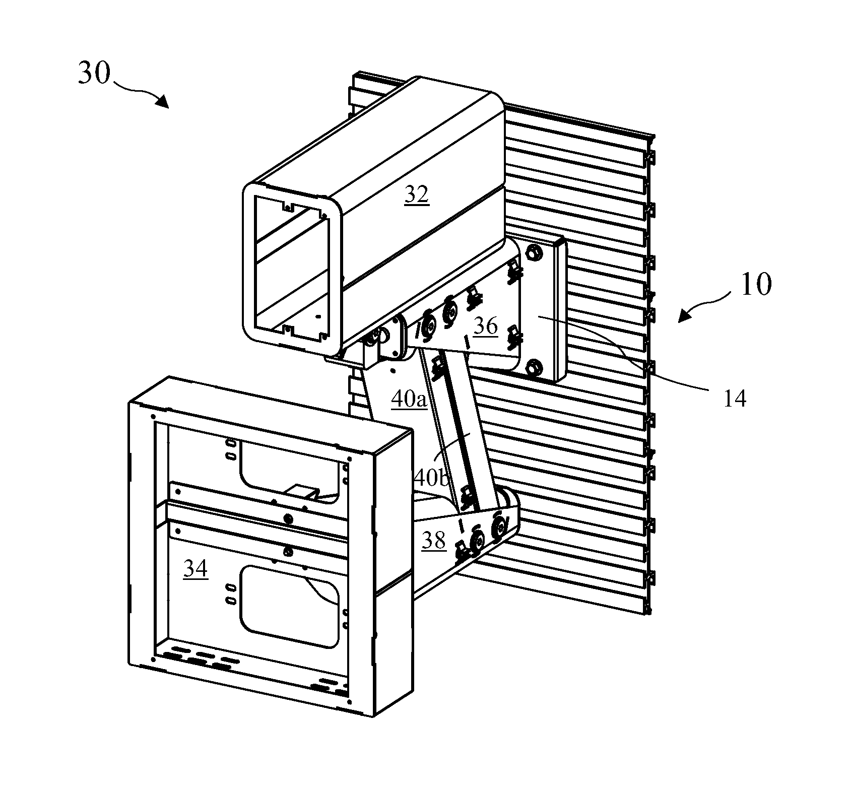
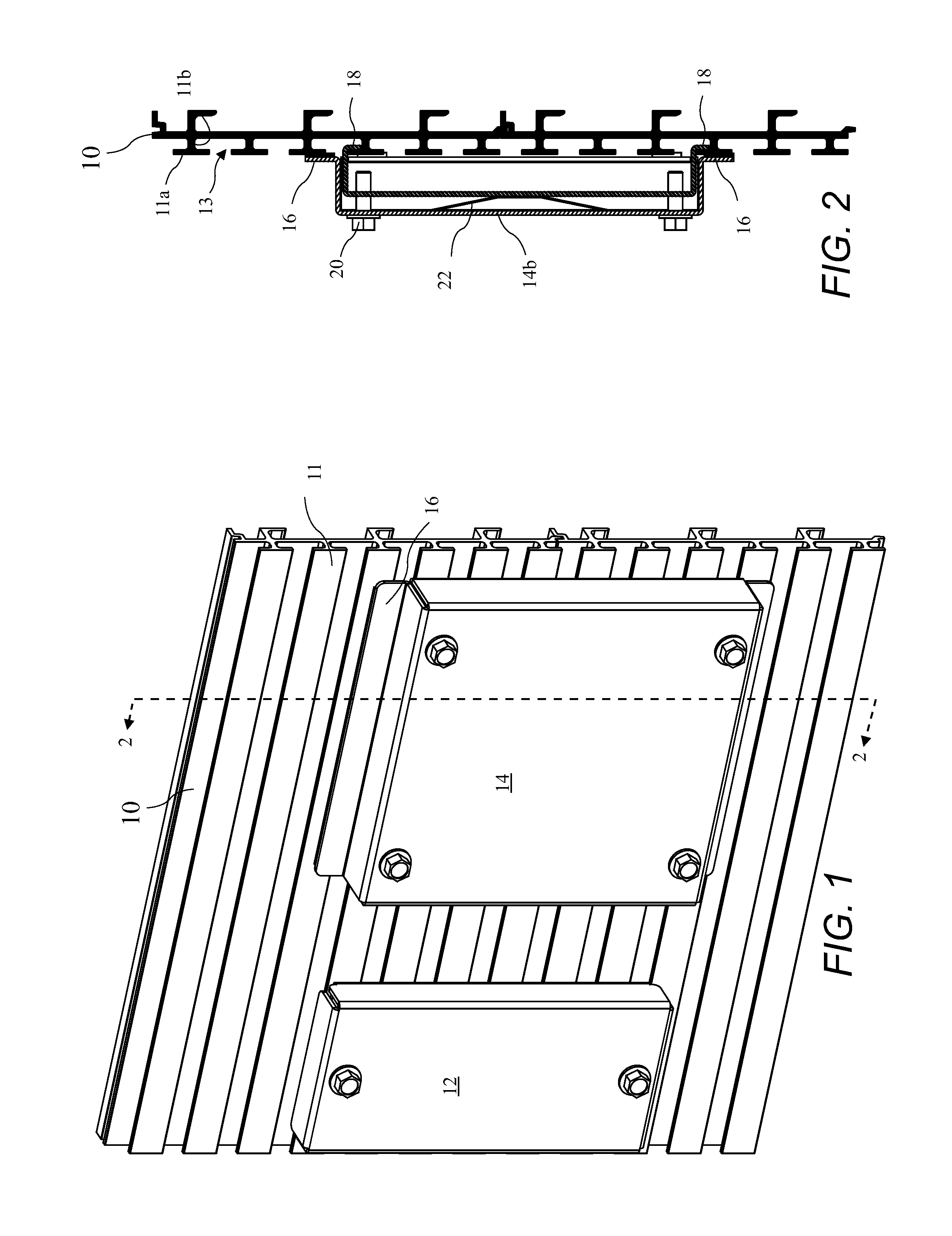
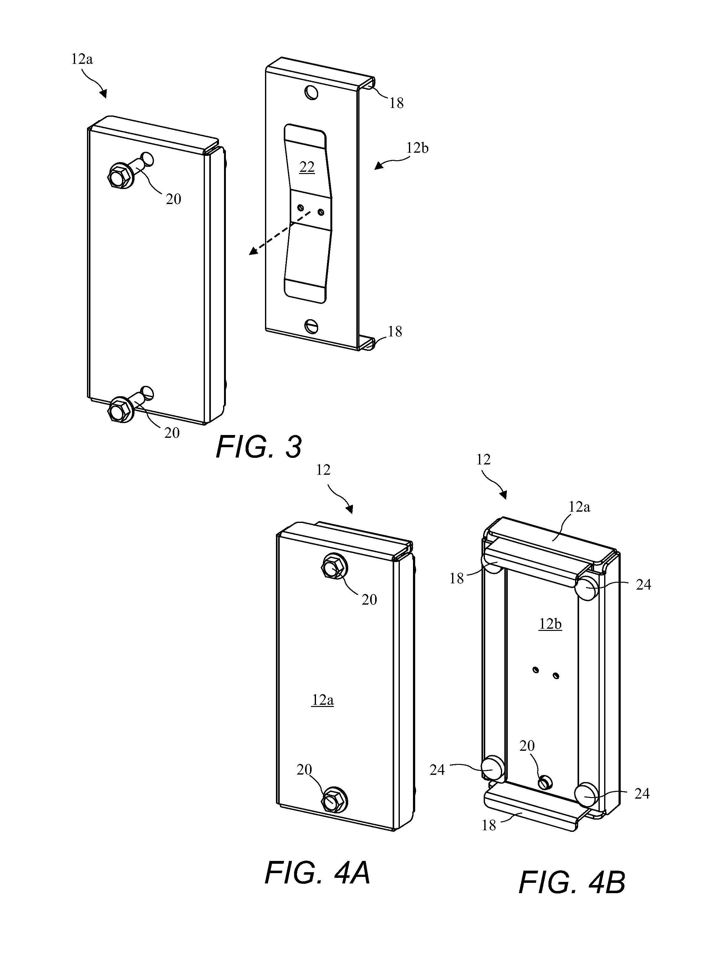
[0073]A perspective view of a slat wall 10 and two embodiments of controlled stress hangers 12 and 14 according to the present invention are shown in FIG. 1, and a cross-sectional view of the slatwall 10 and the controlled stress hanger 14 taken along line 2-2 of FIG. 1 is shown in FIG. 2. The slatwall 10 includes a multiplicity of parallel vertically spaced apart slats 11. Each slat 11 includes a vertical face 11a and a horizontal standoff 11b. Open spaces 13 between consecutive slats 11 allow attachment of the controlled stress hangers 12 and 14 to the slat wall 10. The controlled stress hangers 12 and 14 include outer and inner lips 16 and 18 r...


PUM


Abstract

A display mount is attached to a slatwall using an improved slatwall hanger. The display mount includes vertically pivoting arms providing forward and rearward movement of the display with only slight vertical movement. The slatwall hanger is attached to the slatwall by sandwiching at least one vertical face of a slat between a cover and a clamping member. The cover includes at least one outer lip residing against the front of the vertical face and the clamping member includes at least one inner lip residing against the rear of the vertical face. The clamping member is biased away from the cover by a spring to facilitate insertion of the inner lips between open spaces between consecutive slats. Screws connect the clamping member to the cover and are tightened to grasp the vertical slat face between the lips.

Description

BACKGROUND OF THE INVENTION[0001]The present invention relates to display mounts and in particular to an improved display mount including an improved load bearing slatwall equipment hanger.[0002]In some control center environments, visual access to displays is critical in performing vital functions. Display mounts must provide adjustment for the best viewing positions to minimize fatigue. Known monitor mounts include stacked pivoting arms which provide movement in literally any direction. In some applications there is a desire to restrict movement to in-out for the arm while maintaining a tilt / pivot motion of the monitor. Such in-out motion could be achieved using a parallel horizontal arm structure. Unfortunately, parallel horizontal arms cannot efficiently support the weight of some monitors.[0003]Other known display mounts include slides for forward and rearward motion. At full extension such slides have reduced rigidity and may bind or fail. Additionally, sliding mounts require ...

Claims


Application Information

Patent Timeline
Patent Type & Authority Applications(United States)
IPC IPC(8): F16M13/02F16M11/06F16M11/18
CPCF16M13/022F16M11/06F16M11/18F16M13/02F16M11/10F16M11/2014F16M11/2092F16M11/24F16M2200/044F16M2200/063
Inventor SIMON, TREVORKIM, DANIEL SHIN
Owner RUSS BASSETT
Why Eureka
Try Eureka