Innerl tightening mechanism for footwear

Inactive Publication Date: 2002-09-19
SALOMON SA
View PDF0 Cites 63 Cited by
  • Summary
  • Abstract
  • Description
  • Claims
  • Application Information

AI Technical Summary

Benefits of technology

0009] Therefore, one of the objects of the present invention is to propose an inner tightening mechanism adapted to equip an article of footwear having a flexible or

Problems solved by technology

However, it does not improve the overall precision of the boot, because the tight

Method used


Image

  • Innerl tightening mechanism for footwear
  • Innerl tightening mechanism for footwear
  • Innerl tightening mechanism for footwear

Examples


Example

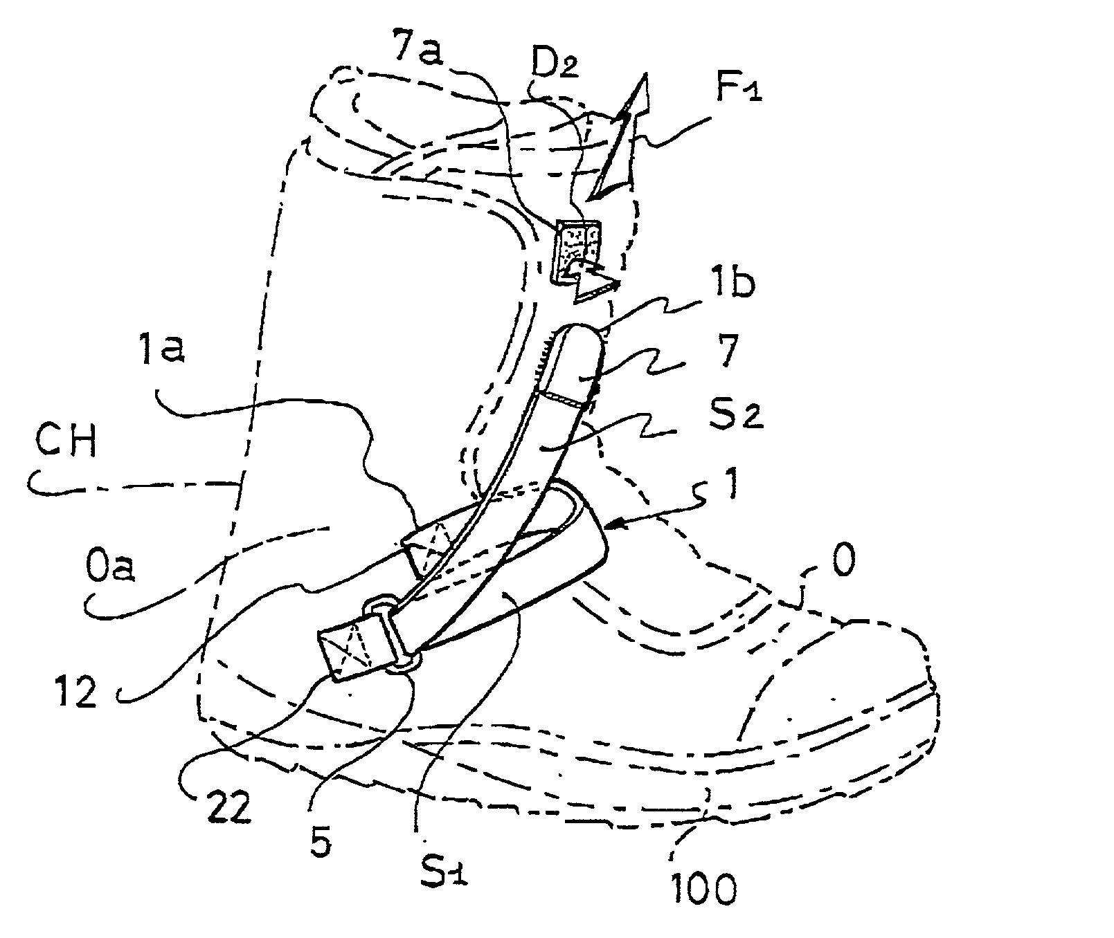
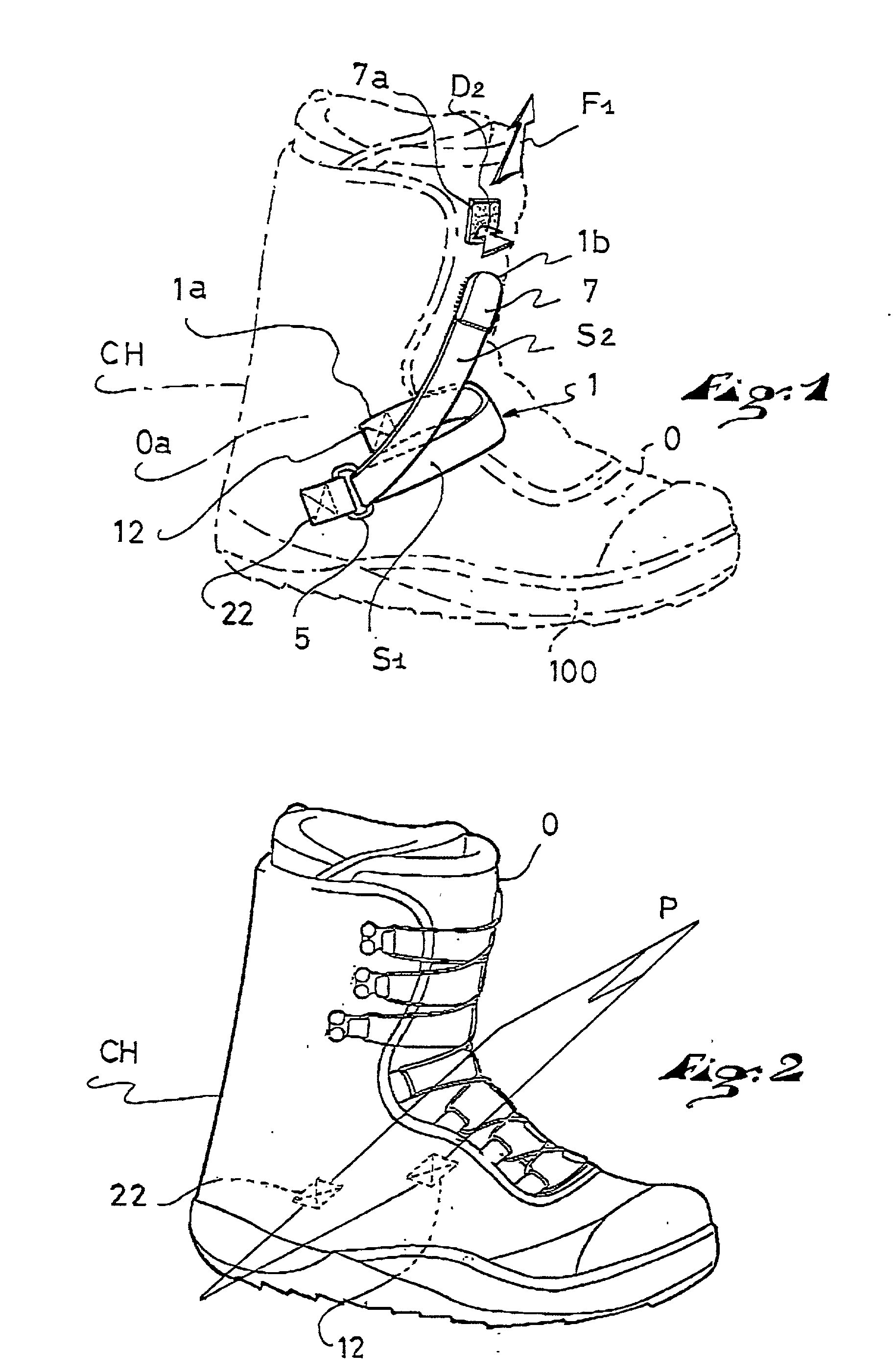
[0025] In FIGS. 1-5, the article of footwear CH shown is a boot having a flexible or semi-rigid upper adapted for snowboarding. A boot having a semi-rigid upper here is a boot with a flexible upper including a more or less large proportion of rigid reinforcements positioned either within or outside the upper O, and adapted to better transmit the forces and supports, but also to protect from impacts.

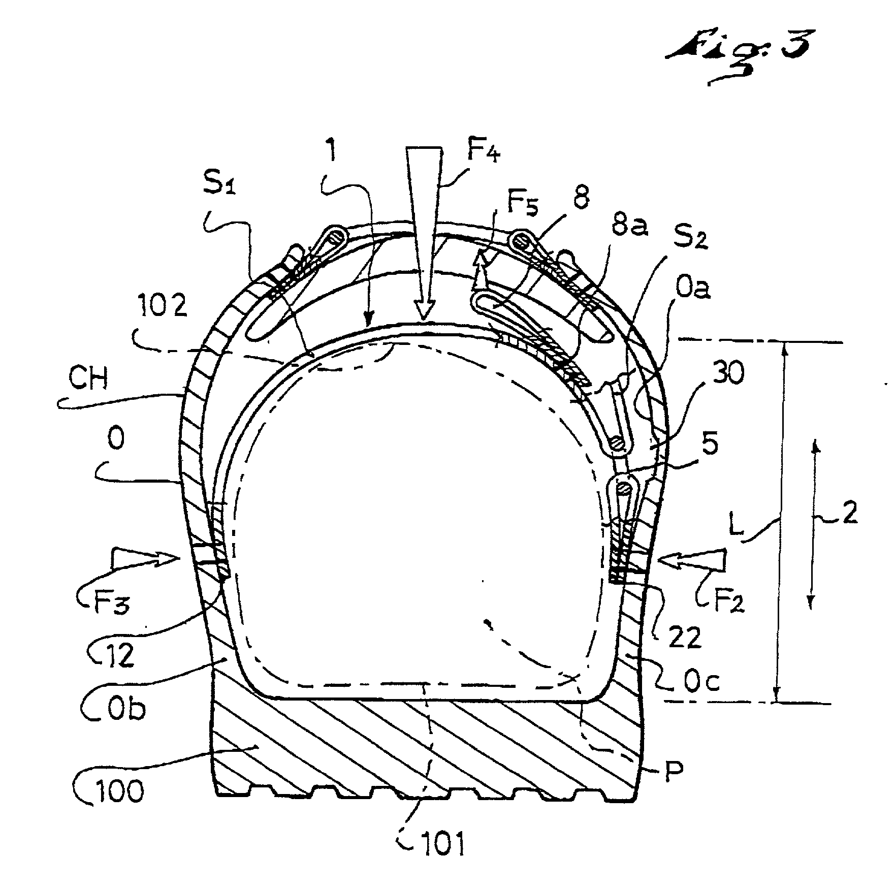
[0026] In FIG. 1, the article of footwear CH is shown in broken lines in order to better illustrate the inner tightening mechanism. The article of footwear CH includes a flexible or semi-rigid upper O which is mounted on a sole 100. The tightening mechanism, which is arranged within the upper O, incudes a retention band 1 that is connected to the inner surface Oa of the upper O by at least two anchoring points 12, 22, fixed on the lateral and medial sides, respectively, of the upper O. This retention band 1 partially surrounds the foot, between the two anchoring points 12, 22, in the area...


PUM


Abstract

An inner tightening mechanism adapted to equip an article of footwear having a flexible or semi-rigid upper. The inner tightening mechanism includes a retention band that is connected to the inner surface of the upper by at least two anchoring points fixed on the lateral and medial sides, respectively, of the flexion in the direction of the heel, and at least one anchoring point is positioned substantially above the sole.

Description

BACKGROUND OF THE INVENTION[0001] 1. Field of the Invention[0002] The present invention relates to an inner tightening mechanism adapted to equip an article of footwear that can be used, particularly, but in a non-limiting manner, for sporting activities.[0003] The articles of footwear thus equipped are intended especially for snowboarding, mounting hiking, in-line roller skating, and ice skating, etc., i.e., for those sports that require the foot to be properly held.[0004] 2. Description of Background and Relevant Information[0005] In the prior art, there are numerous inner tightening systems that hold the foot in the flexion fold area, in the direction of the heel of the boot. However, these systems, in particular that which is described in the document EP 146 502, are associated with boots having a rigid upper, such as alpine ski boots which are constituted of a plastic shell. The inner tightening is connected to the shell in the area where the shell and of the sole are joined in...

Claims


Application Information

Patent Timeline
IPC IPC(8): A43B5/04A43B7/18A43C11/14A63C10/00A63C17/06
CPCA43B5/0401A43B5/0405A43B5/0445A43B7/18A43C11/1493A63C10/00A63C17/06
Inventor BORSOI, BRUNOBASSO, FABIO
Owner SALOMON SA
Why Eureka
Try Eureka