Image-recording device for a printing form, having an array of VCSEL light sources

a technology of printing form and light source, which is applied in the direction of lasers, semiconductor lasers, printing, etc., can solve the problems of reducing manufacturing efficiency, requiring expensive optical lens systems, and complex laser radiation focusing, and achieves simple optics, long system service life, and improved beam properties

a technology of printing form and light source, which is applied in the direction of lasers, semiconductor lasers, printing, etc., can solve the problems of reducing manufacturing efficiency, requiring expensive optical lens systems, and complex laser radiation focusing, and achieves simple optics, long system service life, and improved beam properties

US20020129723A1Inactive Publication Date: 2002-09-19HEIDELBERGER DRUCKMASCHINEN AG

Image

  • Image-recording device for a printing form, having an array of VCSEL light sources
  • Image-recording device for a printing form, having an array of VCSEL light sources
  • Image-recording device for a printing form, having an array of VCSEL light sources

Examples


Embodiment Construction

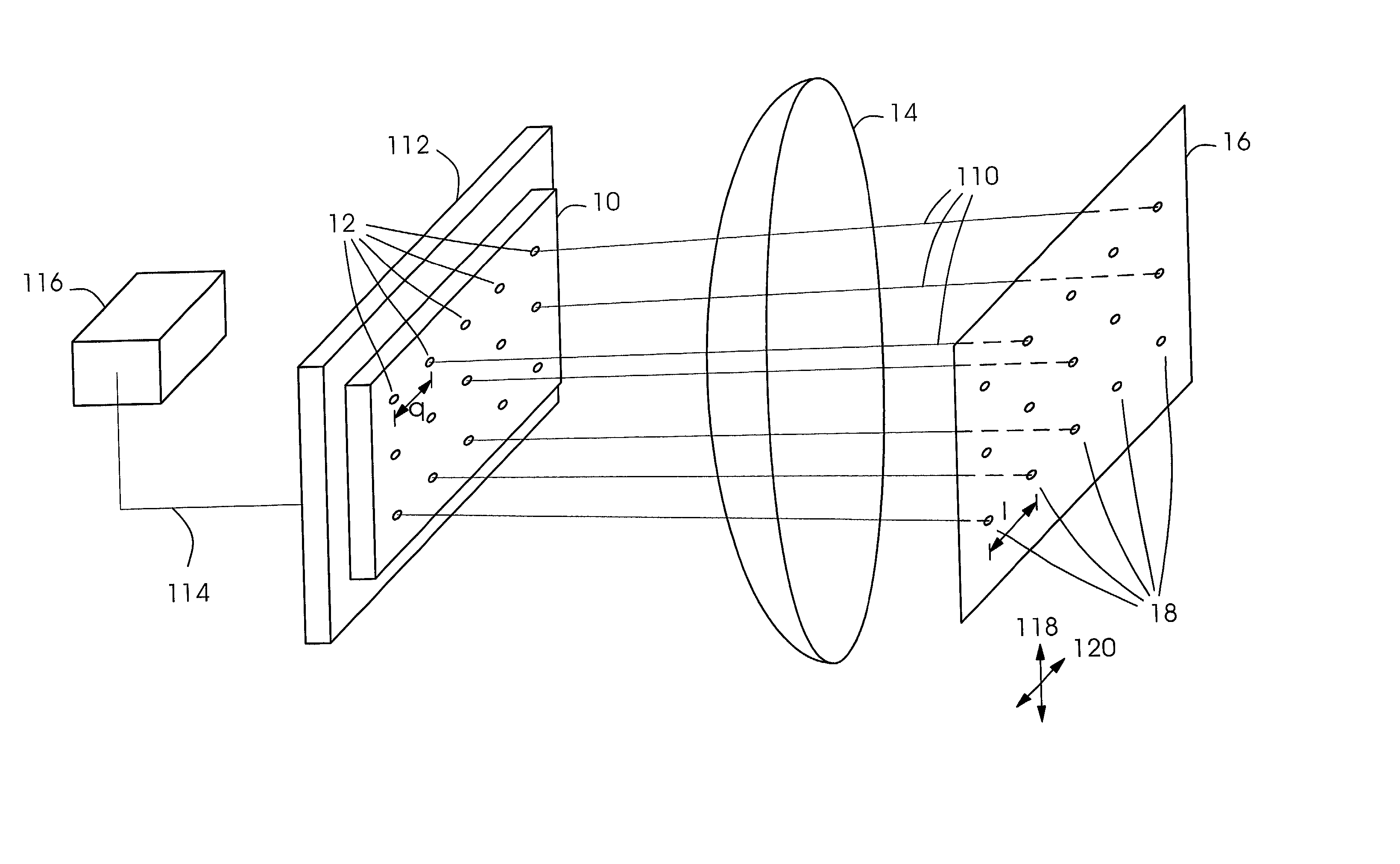
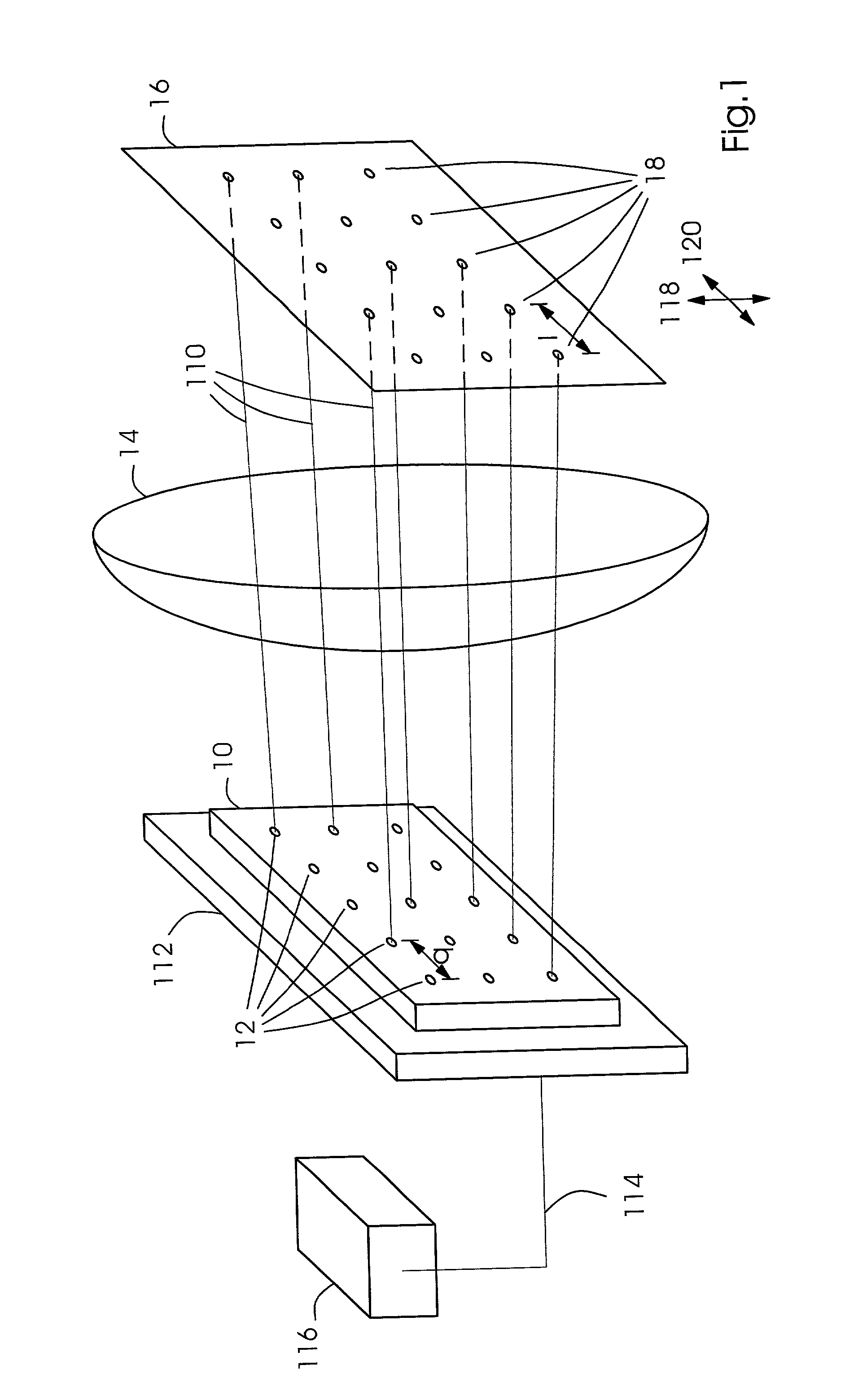
[0039] FIG. 1 shows a schematic representation of a device according to the present invention for recording images on a printing form, including an array 10 of VCSEL light sources 12 and an imaging optics 14 for generating imaging spots on the printing form. The array of light sources 10 has individual emitters, which include VCSEL light sources 12. It is shown by way of example that these VCSEL light sources are spaced apart by a distance q.

[0040] Generally, the distances among the emitters may also differ in the two linearly independent directions defining the surface. As an example, FIG. 1 depicts an array of 3.times.5 VCSEL light sources 12. Generally, however, array 10 includes n.times.m VCSEL light sources 12, n and m being natural numbers.

[0041] Imaging optics 14 is used to generate imaging spots 18 on a printing form 16, adjacent imaging spots being spaced apart by a distance l. In this context, it is unimportant for the essence of the present invention whether distance l be...


PUM

PropertyMeasurementUnit
diameteraaaaaaaaaa
distanceaaaaaaaaaa
phaseaaaaaaaaaa

Abstract

A device for recording images on a printing form, including an array of light sources and imaging optics for generating (n.times.m) imaging spots on a printing form, which is distinguished by the array of light sources including an array of mutually independently controllable VCSEL light sources. One specific imaging spot may be formed on the printing form by combining the light emitted by a subarray of the VCSEL light sources. Due to the advantageous beam properties of VCSEL light sources, such as the small divergence and negligible astigmatism, the device for recording images on printing forms is especially advantageous for use in a printing-form imaging unit or in a print unit.

Description

[0001] Priority to German Application No. 101 11 871.6, filed Mar. 13, 2001 and hereby incorporated by reference herein, is claimed.BACKGROUND INFORMATION[0002] The present invention is directed to a device for recording images on a printing form, including an array of light sources and imaging optics for generating (n.times.m) imaging spots on the printing form, n>1 and m>=1 being natural numbers.[0003] The time it takes to record an image on printing forms, whether it is in a printing-form imaging unit or in a print unit, is substantially determined by the number of available imaging channels. For that reason, typical image-recording devices have a plurality of light sources, at least one light source being assigned to an imaging channel. By way of an image-recording channel, an imaging spot is projected onto the surface of a printing form, enabling printing dots to be placed on the printing form. Many documents in the technical literature deal with the multi-beam image-reco...

Claims


Application Information

Patent Timeline
19 Sep 2002
Publication
US20020129723A1
IPC
B41J2/44; B41C1/10; B41J2/447; B41J2/45; B41J2/455; H01S5/183
CPC
H01S5/4012; B41J2/451
Inventors
BEIER, BERNARD; VOSSELER, BERND