Electrical cable

Inactive Publication Date: 2002-09-19
NEXANS
View PDF0 Cites 27 Cited by
  • Summary
  • Abstract
  • Description
  • Claims
  • Application Information

AI Technical Summary

Benefits of technology

0008] The object of the present invention is to improve the known electrical cables in such a way that they have a s

Problems solved by technology

A disadvantage of this solution, however, is that the electrically conductive cross section of the litz wire is reduced.
The presence of a non-metallic element in the litz wire is also frequently unacceptable.
These proposals, however, have been

Method used


Image

  • Electrical cable
  • Electrical cable

Examples


Embodiment Construction

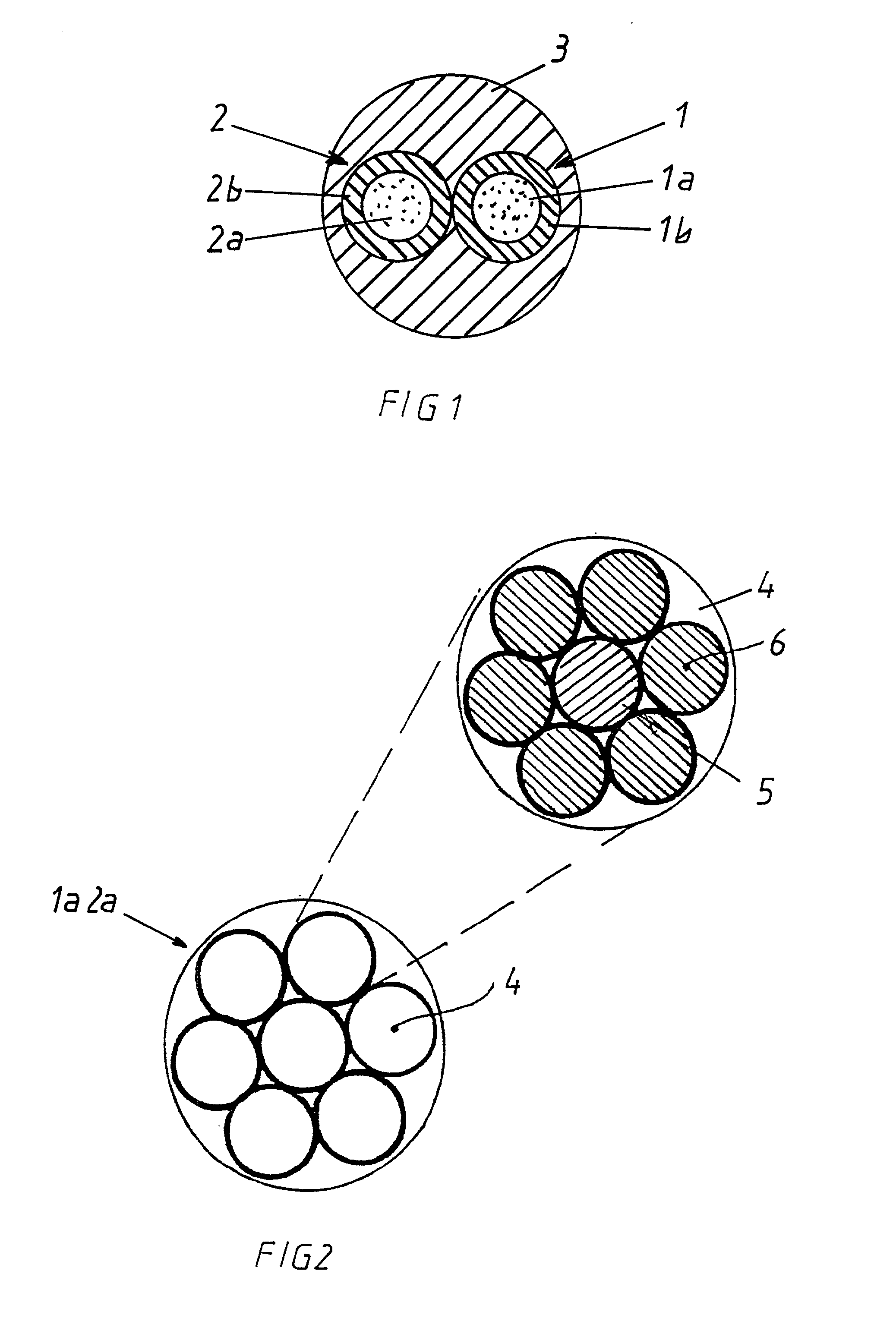
[0014] FIG. 1 is a cross section through an electrical cable, e.g., a sensor cable, comprising two strands 1 and 2 and a sheath 3 surrounding strands 1 and 2. Each strand comprises a conductor 1a or 2a and strand insulation 1b or 2b. The sheath 3 is preferably an extruded polyurethane sheath. The strand insulation 1a or 2b may be made of thermoplastic or cross-linked insulating materials. Preferred is irradiation cross linked polyethylene, polyurethane or a two-layer insulation, such as it is described, for instance, in the prior application 100 36 610.4.

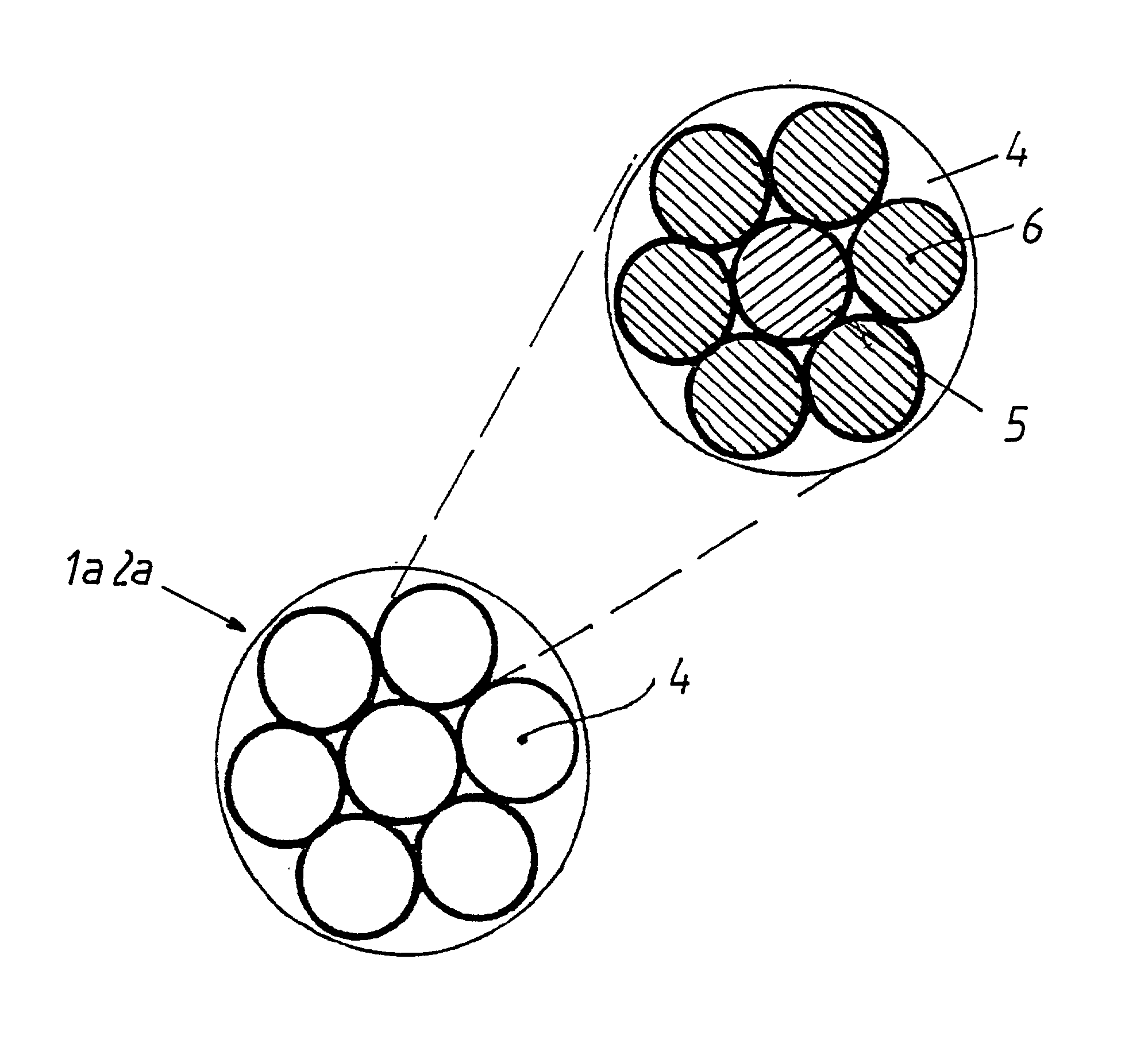
[0015] The conductor 1a or 2a is a multi-wire strand as it is shown in FIG. 2.

[0016] The strand 1a, 2a consists of seven wire bundles 4, six of which are stranded as a layer around a central wire bundle. Each wire bundle 4 has an inner core wire 5 around which six individual wires 7 are stranded. These individual wires 7 are preferably stranded with an alternating direction of lay-which in cable technology is referred to as SZ-stran...


PUM


Abstract

In an electrical cable, particularly a sensor cable, with an electrical conductor (1a, 2a) and an insulating layer (1b, 2b) surrounding the conductor, the conductor (1a, 2a) is made of a plurality of stranded or bunched wire bundles (4). Each wire bundle (4) has a central core wire (5) that is made of a metal with high tensile strength and alternating bending strength and a plurality of copper wires (6) that are stranded around the core wire (5).

Description

[0001] This application is based on and claims the benefit of German Patent Application No. 10101641.7 filed Jan. 16, 2001, which is incorporated by reference herein.BACKGROUND OF THE INVENTION[0002] The present invention relates to an electrical cable with an electrical conductor and an insulating layer surrounding the conductor.[0003] Electrical cables to connect mobile power consumers must be flexible and have a finely or even a very finely stranded conductor, depending on the required flexibility.[0004] For mechanical stressability and flexibility not only the quality and the diameter of the wires are important but particularly also the stranding structure of the conductor. The shorter the lay of the litz wires and the strands, the greater the flexibility and the alternating bending strength.[0005] German Application DE-A-25 19 687 discloses a method for producing a stranded conductor in which a thread of glass-filament yarn is included in the stranding of a plurality of individ...

Claims


Application Information

Patent Timeline
IPC IPC(8): H01B7/04
CPCH01B7/041
Inventor GROEGL, FERDINANDGOEBLMAIER, REINGOLDMANN, THOMAS
Owner NEXANS
Why Eureka
Try Eureka