Piezoelectric vibrator, piezoelectric vibration apparatus for using the same and manufacturing method therefor

a technology of piezoelectric vibration and piezoelectric vibrator, which is applied in the direction of generator/motor, device details, and piezoelectric/electrostrictive device details, etc., can solve the problems of sound quality deterioration and sound pressure drop, and achieve the effect of thin thickness and high sound pressur

Inactive Publication Date: 2002-09-19
TAIYO YUDEN KK
View PDF6 Cites 25 Cited by
  • Summary
  • Abstract
  • Description
  • Claims
  • Application Information

AI Technical Summary

Benefits of technology

0006] It is, therefore, an object of the present invention to provide a piezoelectric vibrator capable of obtaining a higher sound pressure with a smaller diameter thereof, a piezoelectric vibration apparatus for using the piezoelectric vibrator with a smaller diameter thereof and a thinner thickness thereof and a method for manufacturing the piezoelectric vibrator.

Problems solved by technology

Accordingly, the sound pressure is decreased and the sound quality is also deteriorated.

Method used


Image

  • Piezoelectric vibrator, piezoelectric vibration apparatus for using the same and manufacturing method therefor
  • Piezoelectric vibrator, piezoelectric vibration apparatus for using the same and manufacturing method therefor
  • Piezoelectric vibrator, piezoelectric vibration apparatus for using the same and manufacturing method therefor

Examples


example 1

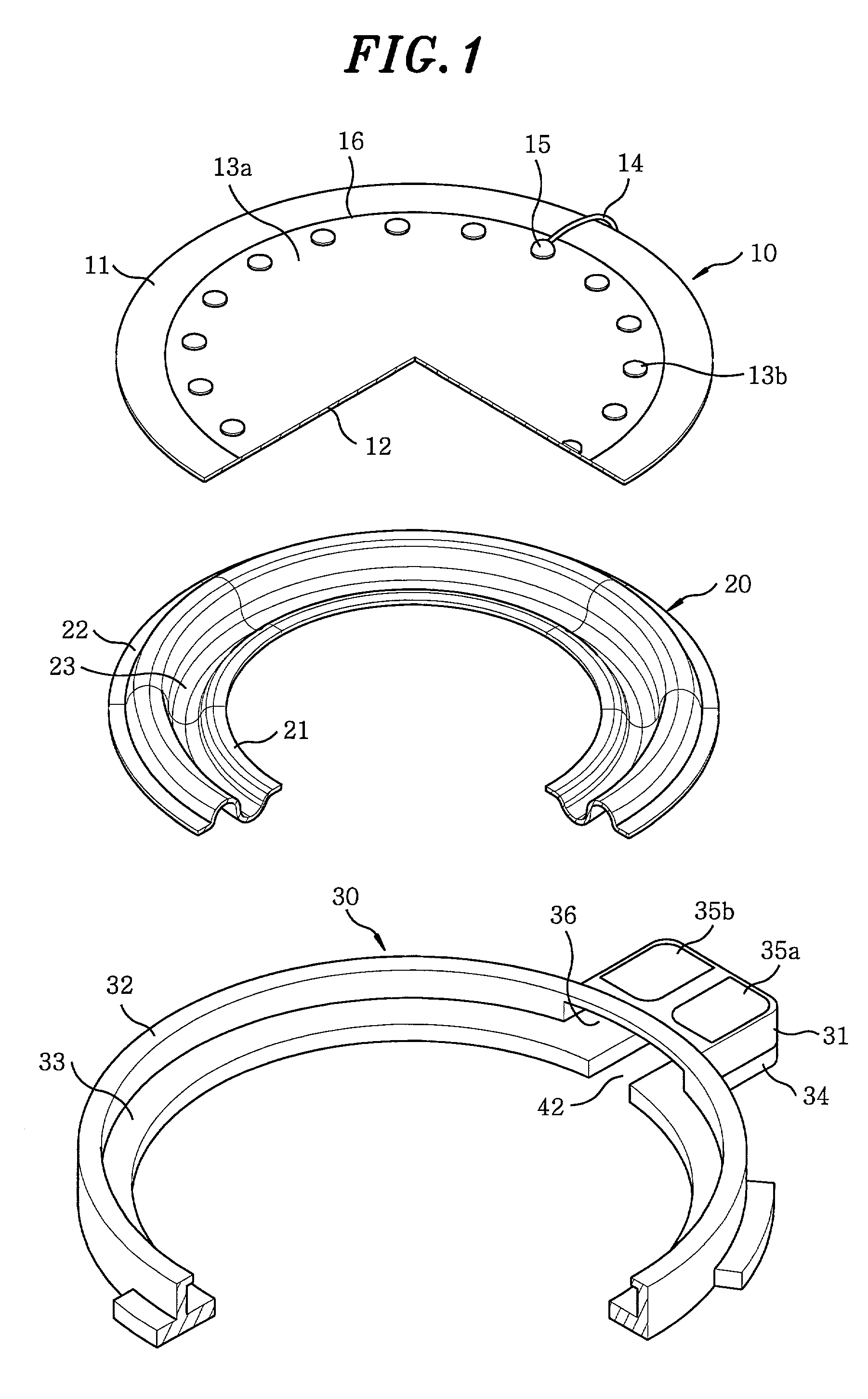
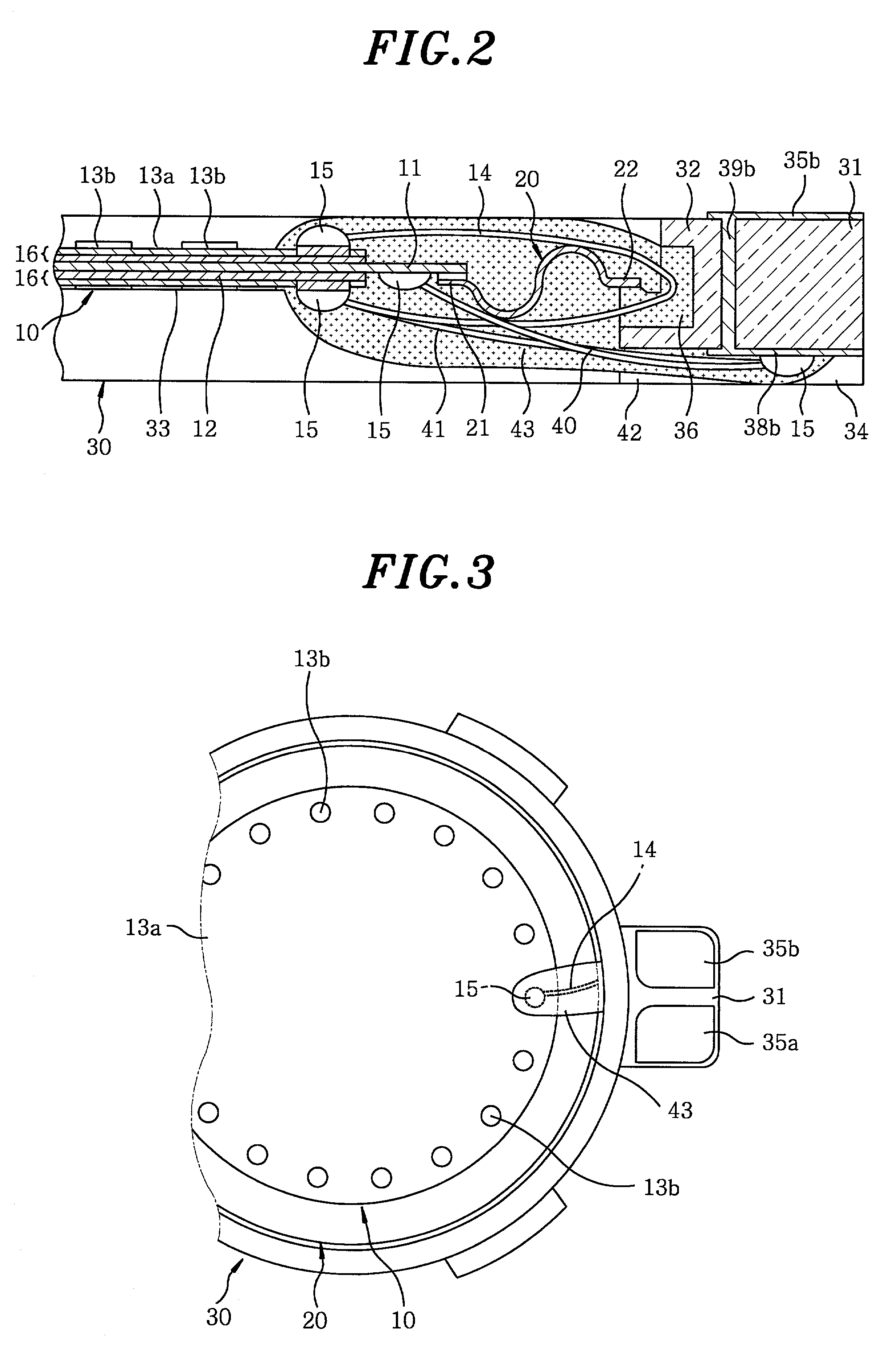
[0030] Referring to FIGS. 1 to 10, there is specifically illustrated a first embodiment in accordance with the present invention. FIG. 1 shows basic components of a piezoelectric vibration apparatus in accordance with the first embodiment of the present invention. Referring to FIG. 2, there is a primary cross-sectional view for illustrating a structure near to two terminals 35a and 35b of the piezoelectric vibration apparatus. Referring to FIGS. 3 and 4, there are shown plan views for partially illustrating an upper and a lower side near to two terminals 35a and 35b of the piezoelectric vibration apparatus. The piezoelectric vibration apparatus has a piezoelectric vibrator 10, a holding element 20 and a frame 30.

[0031] The piezoelectric vibrator 10 has a vibration plate 11 and a piezoelectric device 16 attached thereto, wherein the vibration plate 11 is made of circular metal plate and the piezoelectric device 16 has a piezoelectric film 12 and two electrodes formed on two primary s...

example 2

[0065] Referring to FIGS. 11 to 13, there is shown another embodiment of the present invention. In case the piezoelectric vibrator is used as a speaker for a cellular phone, the driving voltage must be preferably small. Since the amplitude of the sound depends on the absolute value of the displacement of the piezoelectric vibrator, the more driving energy is required to make a loud sound. The driving energy E of the unimorph or the bimorph vibrator in accordance with the present invention may be calculated as follows: 1 E 1 2 d 31 V 2 D 2 S 31 n t

[0066] wherein d.sub.31 is a transverse component of a piezoelectric strain constant of the piezoelectric material, S.sub.31 is a transverse component of an elastic compliance, D is a diameter of the piezoelectric device and V is an applied voltage.

[0067] Accordingly, other than changing the piezoelectric material itself, the driving energy E can be increased by increasing the diameter D and raising the applied voltage V, to thereby increas...

second embodiment

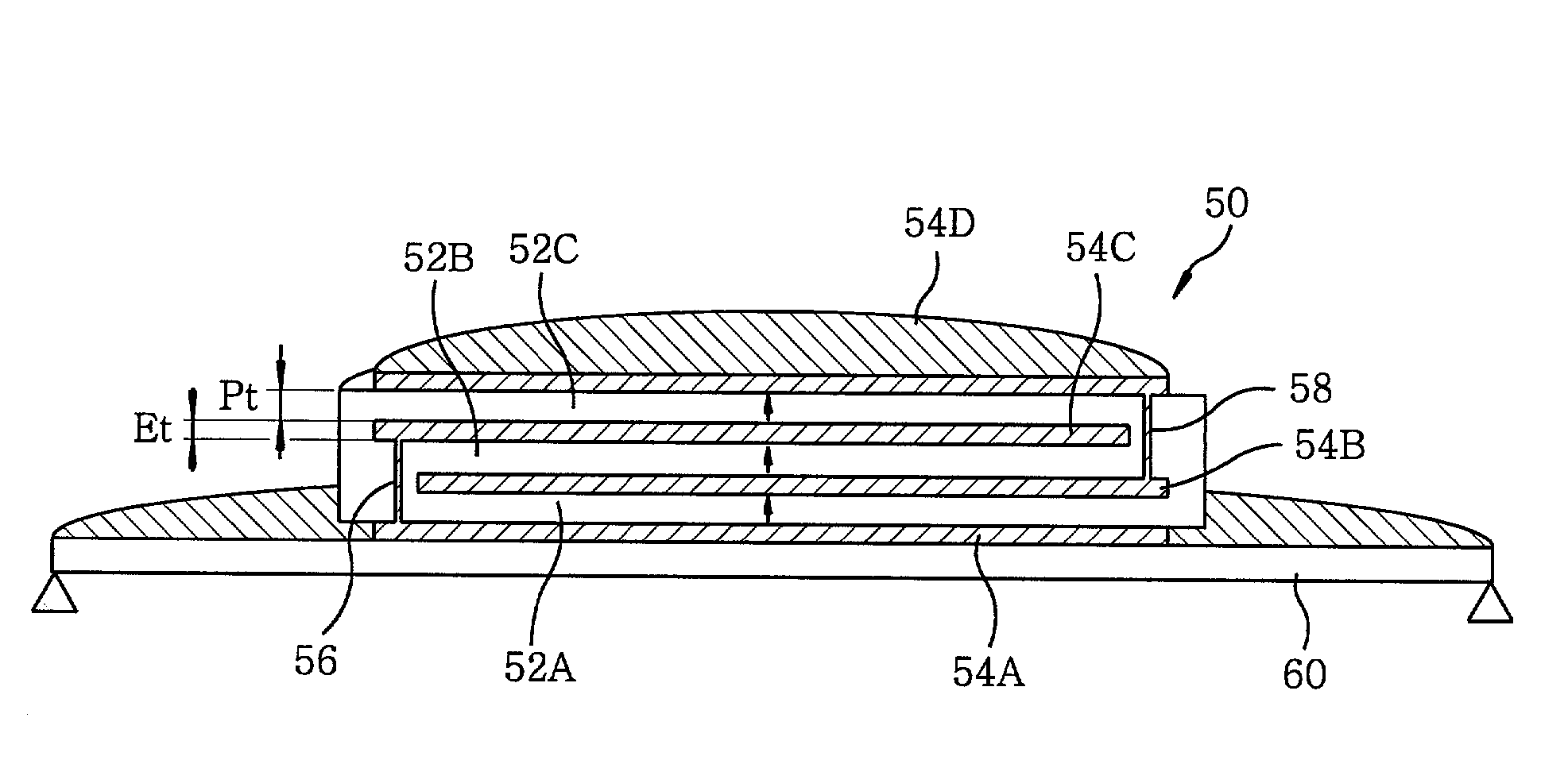
[0074] Referring to FIG. 11, there is shown an enlarged primary view of the piezoelectric vibrator in accordance with the present invention and, referring to FIG. 12A, there is a cross-sectional view of the piezoelectric vibrator shown in FIG. 11. As shown in FIGS. 11 and 12A, the piezoelectric device has a stacking structure. The unimorph piezoelectric vibrator with a disc shape has a vibration plate 60 and a piezoelectric device 50 attached thereon.

[0075] The piezoelectric device 50 has a structure in which a plurality of piezoelectric films 52A to 52C made of piezoelectric translator (PZT) and a multiple of electrodes 54A to 54D are alternately stacked. A predetermined number of piezoelectric films 52A to 52C and another predetermined number of the electrodes 54A to 54D are alternately stacked and, then, are cofired on the whole to form the piezoelectric device 50. The piezoelectric device 50 is attached around the center of the vibration plate 60 by an adhesive material.

[0076] T...


PUM


Abstract

A piezoelectric vibrator with a smaller diameter may have a higher sound pressure to obtain a piezoelectric vibration apparatus with a smaller diameter and a thinner thickness. Although the primary electrode is uniformly coated on the primary side, it is not coated on all the primary side of the piezoelectric film and it is made of a continuous mesh metal film. Accordingly, a driving voltage may be applied on the piezoelectric film while there are some portions on the primary side on which the metal film is partially uncoated so that the curvature restraint of the piezoelectric film due to the primary electrode may be reduced. The contact electrode with a higher metal film occupation ratio than that of the primary electrode is coated so that the contact electrode may be used as a soldering portion for connecting thereto the terminal.

Description

FIELD OF THE INVENTION[0001] The present invention relates to a piezoelectric vibrator, a piezoelectric vibration apparatus for using the piezoelectric vibrator and a method for manufacturing the piezoelectric vibrator; and, more particularly, to a piezoelectric vibrator capable of obtaining a higher sound pressure with a smaller diameter thereof and a thinner thickness thereof.BACKGROUND OF THE INVENTION[0002] In a conventional piezoelectric vibration apparatus, a piezoelectric vibrator has been used. The piezoelectric vibrator includes a vibration plate and a piezoelectric film attached on the vibration plate. The vibration plate is made of a circular metal plate and the piezoelectric film has a circular piezoelectric ceramic plate and two electrodes installed, respectively, on two sides of the circular piezoelectric ceramic plate. If a driving voltage is applied between two electrodes of the piezoelectric film, the piezoelectric film may be displaced along a direction orthogonal ...

Claims


Application Information

Patent Timeline
Patent Type & Authority Applications(United States)
IPC IPC(8): H01L41/09H04R17/00
CPCH04R17/00H01L41/0833H01L41/0973H10N30/503H10N30/2047
Inventor HAMADA, HIROSHIMATSUI, YUKIHIROINOMATA, YASUYUKIOIKAWA, HIDEKI
Owner TAIYO YUDEN KK
Why Eureka
Try Eureka