

Optical pickup, information processing apparatus, optical information recording and reproducing method
a technology of information processing apparatus and optical information, applied in the field of optical information recording and reproducing method, can solve the problems of increasing costs and upsizing the apparatus
- Summary
- Abstract
- Description
- Claims
- Application Information
AI Technical Summary
Benefits of technology
Problems solved by technology
Method used
Image


Examples
embodiment 1
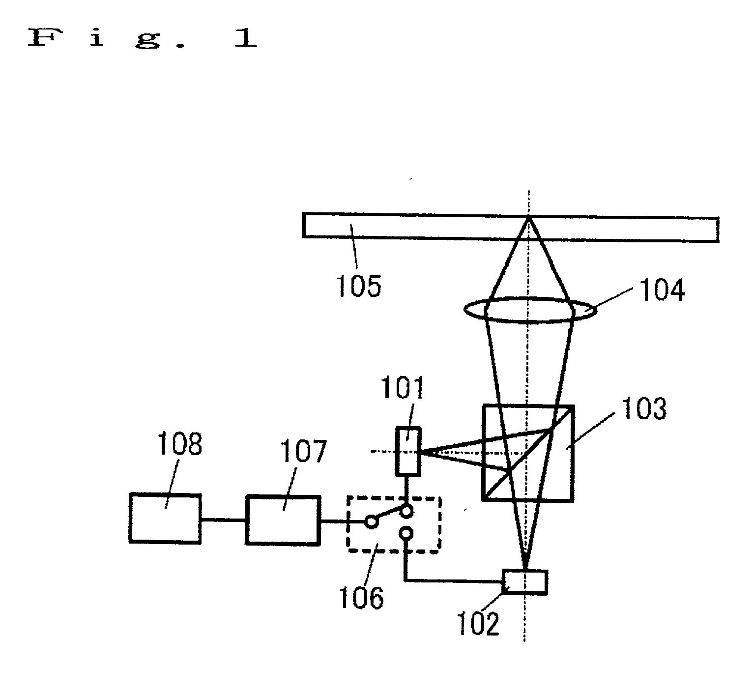
[0099] (Embodiment 1)
[0100] FIG. 1 is a block diagram of an optical pickup according to an embodiment 1 of the present invention. Reference numerals 101 and 102 denote light source units having light sources of mutually different wavelengths, where the light source unit 101 has a shorter wavelength than that of the light source unit 102. In addition, reference numeral 103 denotes a BS, 104 denotes a condenser lens, 105 denotes a record medium, 106 denotes switching means, 107 denotes a drive circuit, and 108 denotes a control circuit. As an operation of recording and reproducing optical information is the same as the past example in the operations of the above-mentioned respective means, description thereof will be omitted. The switching means 106 switches a signal from the drive circuit 107 to the light source unit 101 or 102 according to the type of the record medium 105.
[0101] It is possible, by this configuration, to drive both the light source units 101 and 102 on the single dr...
embodiment 2
[0116] (Embodiment 2)
[0117] FIG. 3 is a block diagram of the optical pickup of an embodiment 2 of the present invention. In the drawing, the portions that are the same as or equivalent to FIGS. 1 and 2 are numbered likewise and detailed description thereof will be omitted. In addition, reference numeral 301 denotes the light source unit including the first light source of the present invention, and 302 denotes the light source unit including the second light source thereof. In FIG. 3(a) , the lights from the two light source units 301 and 302 are condensed on the record medium 105 via a BS 303 and the condenser lens 104 so as to record and reproduce the information. Here, the light source unit 301 records and reproduces the information, and the light source unit 302 just reproduces the information. At this time, the wavelengths of the light source units 301 and 302 may be either mutually different or the same.
[0118] When comparing the light source units 301 and 302, the light source...
embodiment 3
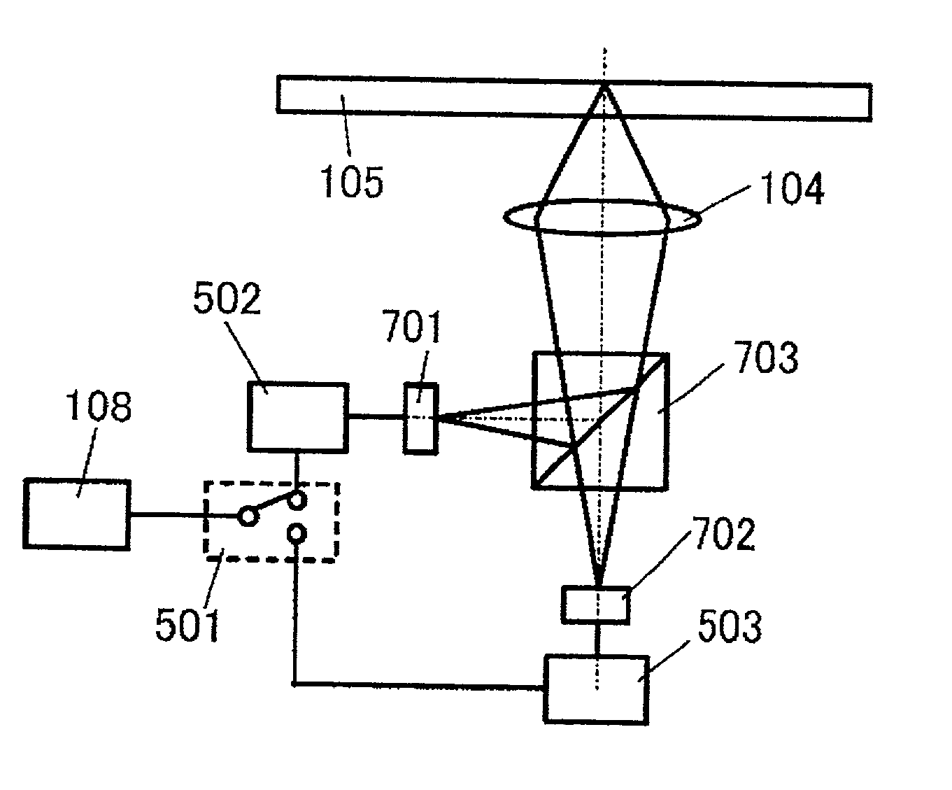
[0126] (Embodiment 3)
[0127] FIG. 5 is a block diagram of an embodiment 3 of the present invention. Reference numerals 101 and 102 are the light source units having the light sources of mutually different wavelengths, where the light source unit 101 has the shorter wavelength than that of the light source unit 102. In addition, reference numeral 103 denotes the BS, 104 denotes the condenser lens, 105 denotes the record medium, 501 denotes the switching means, 502 denotes the drive circuit equivalent to the first drive circuit of the present invention, 503 denotes the drive circuit equivalent to the second drive circuit of the present invention, and 108 denotes the control circuit. As an operation of recording and reproducing the optical information is the same as the past example and the embodiment 1, description thereof will be omitted. The switching means 501 switches the signal from the control circuit 108 to the drive circuit 502 for the light source unit 101 or the drive circuit...
PUM
 Abstract
Description
Claims
Application Information