Device for feeding article to a blister band

Inactive Publication Date: 2002-09-26
IMA IND MASCH AUTOMATICHE SPA
View PDF0 Cites 16 Cited by
  • Summary
  • Abstract
  • Description
  • Claims
  • Application Information

AI Technical Summary

Benefits of technology

0030] Another object of the present invention is to propose a filling device which ensures high reliability

Problems solved by technology

Consequently, the accumulated articles tend to enter the empty blisters and translate together with the belt, thus leaving the container.
However, all the above described known systems have a series of problems due to the typical characteristics of the filling technique being used.
First of all, the articles, specially if very fragile, can be scratched or chipped by repeated pushes and reciprocal friction against the band surface, or again

Method used


Image

  • Device for feeding article to a blister band
  • Device for feeding article to a blister band
  • Device for feeding article to a blister band

Examples


Embodiment Construction

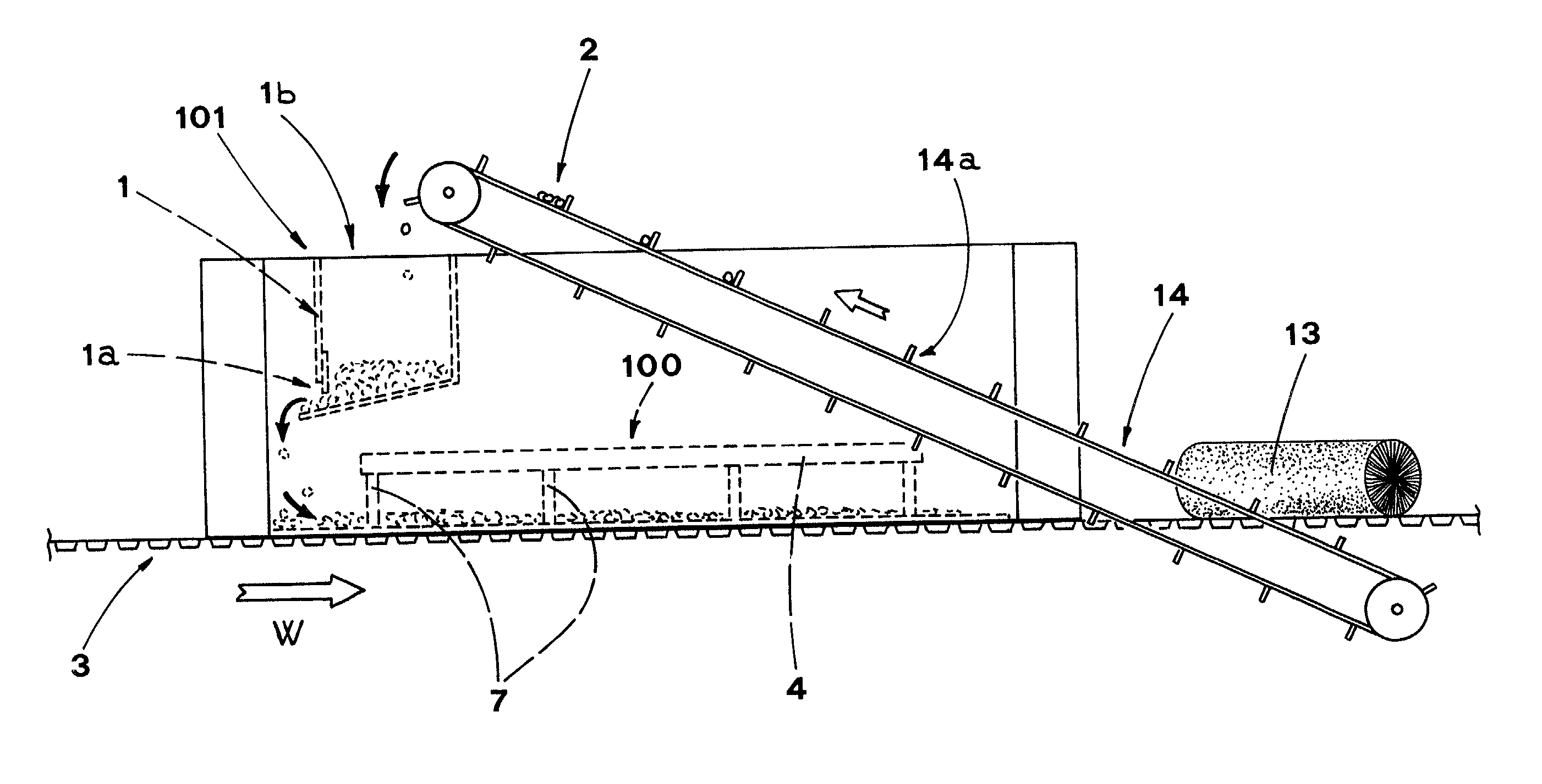
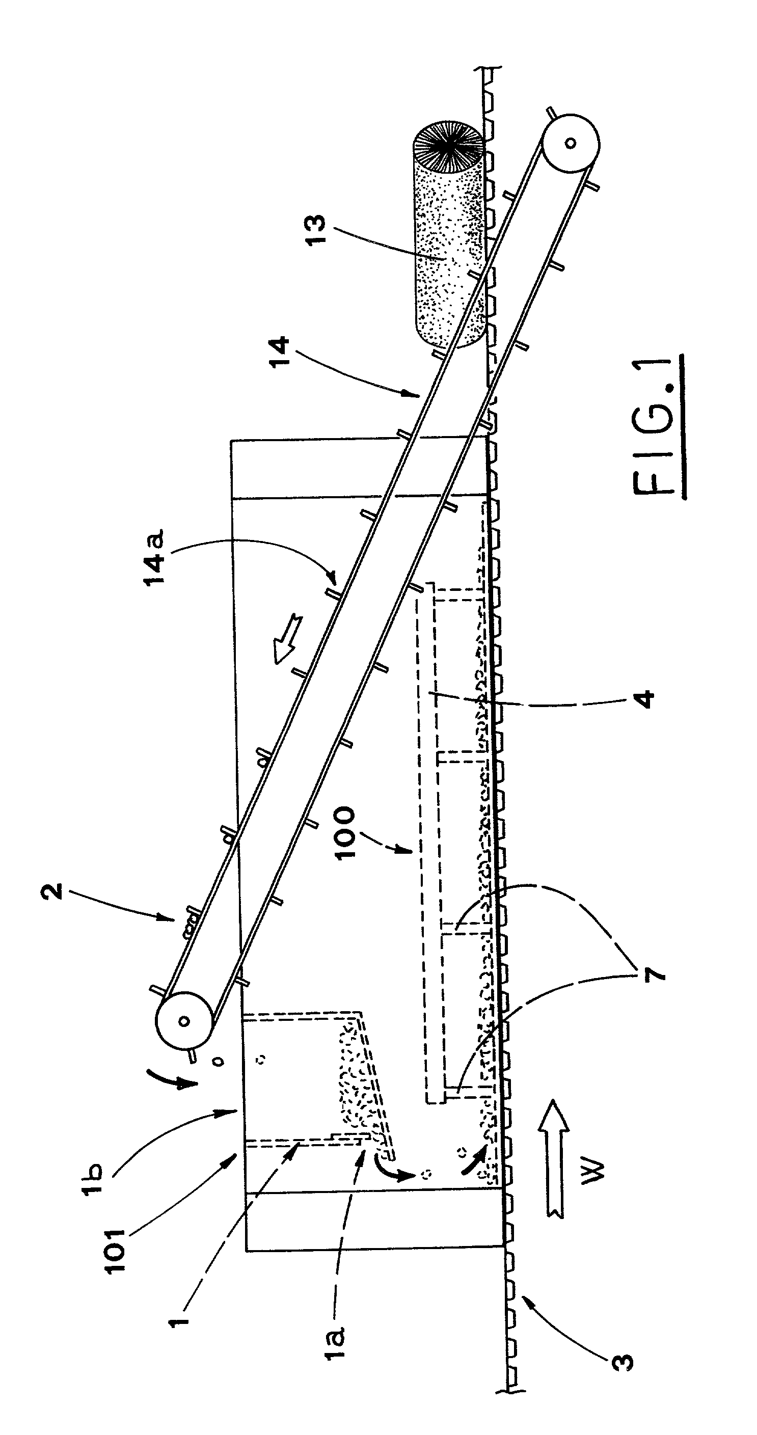
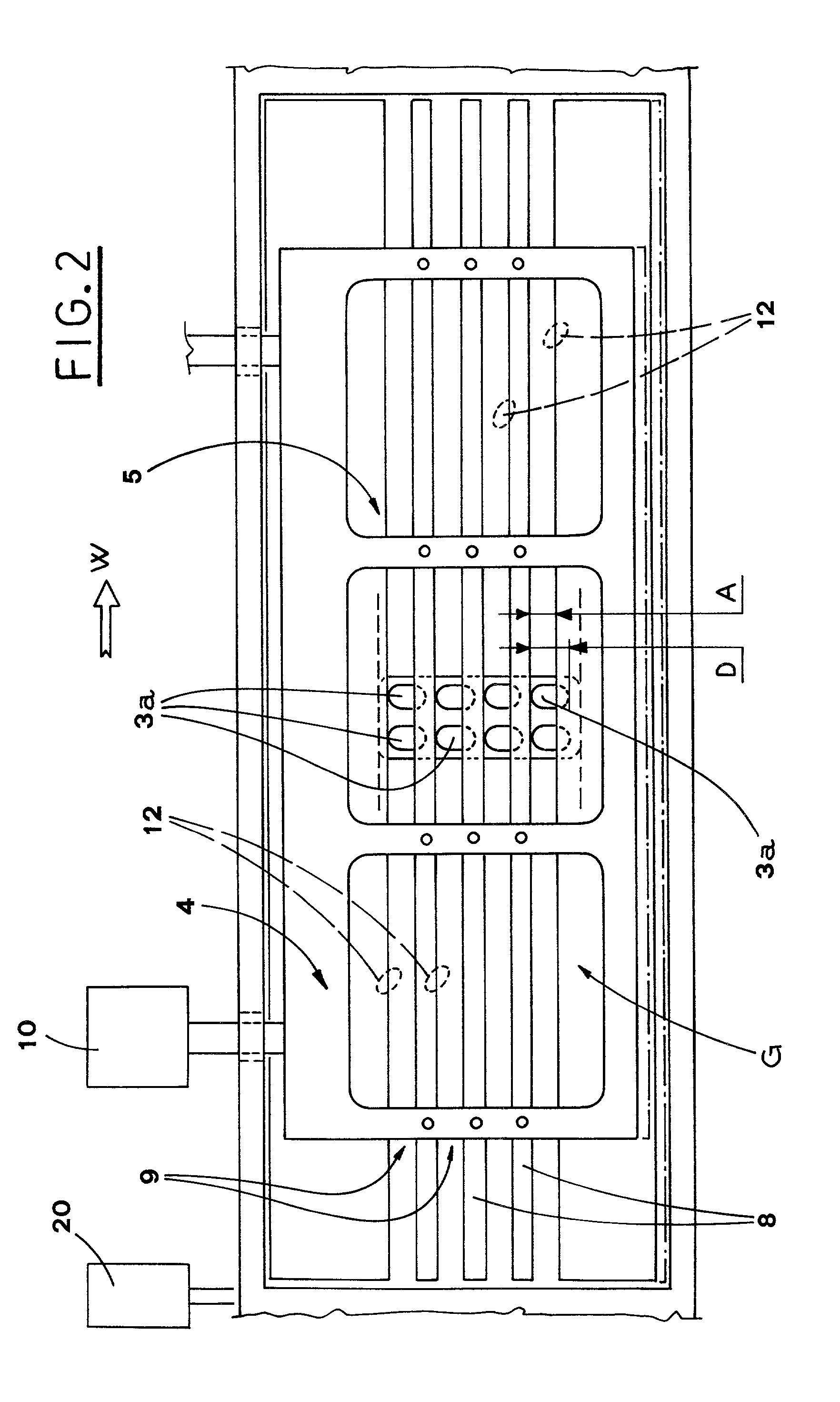
[0045] With reference to the above figures, the reference numeral 3 indicates a blister band with a plurality of longitudinal rows of blisters 3a aimed at receiving corresponding articles 2.

[0046] The blister band 3, moved longitudinally by known and not shown conveying means in a corresponding movement direction W, is supported and guided by a suitable supporting surface 11 (FIG. 6).

[0047] The device 100, being the subject of the present invention, includes substantially a support structure 4, situated over the blister band 3 and featuring, in its lower part, two chutes, first 6a and second 6b.

[0048] The chutes 6a, 6b, aimed at conveying and delimiting the articles 2 coming from a feeding station 101 to the blister band 3 situated below, have corresponding lower edges, first 60a and second 60b (FIG. 3), situated substantially immediately above the blister band 3.

[0049] The lower part of the support structure 4 supports relative bars 7 (FIGS. 1, 3 and 6), which in turn support a plu...


PUM

PropertyMeasurementUnit
Flexibilityaaaaaaaaaa
Dimensionaaaaaaaaaa

Abstract

A device (100) for feeding articles (2) to a blister band (3) moving below and having at least one row of blisters (3a) made therein for receiving corresponding articles (2). The row of blisters is parallel to the blister band forward direction (W). The device (100) has a grid (G) situated over the blister band (3), with at least one longitudinal channel (9), facing the longitudinal row of blisters (3a). A station (101) is provided for feeding the articles (2) to the grid (G), while oscillating means (10,20) generate a relative oscillating motion between the grid (G) and the corresponding blister band (3), to facilitate stabile introduction of the articles (2) into the corresponding blisters (3a) present along said longitudinal channel (9).

Description

[0001] The present invention relates to automatic packaging, into blister packs, of various articles, such as tablets, pills, capsules and the like, in particular rhomboid and / or oblong.[0002] In the described case, the present invention relates to a device for feeding articles to a blister band.DESCRIPTION OF THE PRIOR ART[0003] At present, pharmaceutical products are packaged into blister packs, formed by a strip formed with a series of blisters for containing articles.[0004] The strip is usually closed by a sheet of e.g. aluminium, and the articles are withdrawn, according to known techniques, by breaking the aluminium sheet.[0005] The blister packs are obtained by forming, in a suitable molding station, one or more rows of blisters in a continuous band of appropriate material, usually heat-formable or aluminium; afterwards the blister band passes through a filling station, where at least one article is introduced into each obtained blister; finally, the blister band is definitel...

Claims


Application Information

Patent Timeline
IPC IPC(8): B65B1/06B65B9/04B65B35/34B65B37/02B65B37/04
CPCB65B9/045B65B35/34
Inventor BARONCINI, IVANO
Owner IMA IND MASCH AUTOMATICHE SPA
Why Eureka
Try Eureka