Fuel cell stack

a fuel cell and stack technology, applied in the field of fuel cell stacks, can solve the problems of deteriorating the power generation characteristics of the fuel cell stack, difficult to pressurize the cell units with an equivalent tightening force, and extremely large thermal stress applied to the cell stack, and achieves the effect of convenient pressurization

Inactive Publication Date: 2002-10-03
HONDA MOTOR CO LTD
View PDF1 Cites 48 Cited by
  • Summary
  • Abstract
  • Description
  • Claims
  • Application Information

AI Technical Summary

Benefits of technology

[0018] It is an object of the present invention to provide a fuel cell stack having a compact size and a light weight in which a stack of cell units can be easily pressurized with an equivalent tightening force, and it is possible to maintain the electric contact between constitutive members suitably.

Problems solved by technology

As a result, any contact failure occurs in the cell stack 13 and the internal resistance is increased, deteriorating the power generation characteristics of the fuel cell stack 10 in some cases.
Although a compact size can be realized for the fuel cell stack in any one of the foregoing cases, it is difficult to pressurize the cell units with an equivalent tightening force.
As a result, an extremely large thermal stress is applied to the cell stack.
Consequently, the contact failure occurs in the cell stack, increasing the internal resistance of the fuel cell stack.

Method used


Image

  • Fuel cell stack
  • Fuel cell stack
  • Fuel cell stack

Examples


Embodiment Construction

[0038] The fuel cell stack according to the present invention will be exemplified by a preferred embodiment below, which will be explained in detail with reference to the accompanying drawings. The same constitutive components as the constitutive components shown in FIGS. 5 and 6 are designated by the same reference numerals, detailed explanation of which will be omitted in some cases.

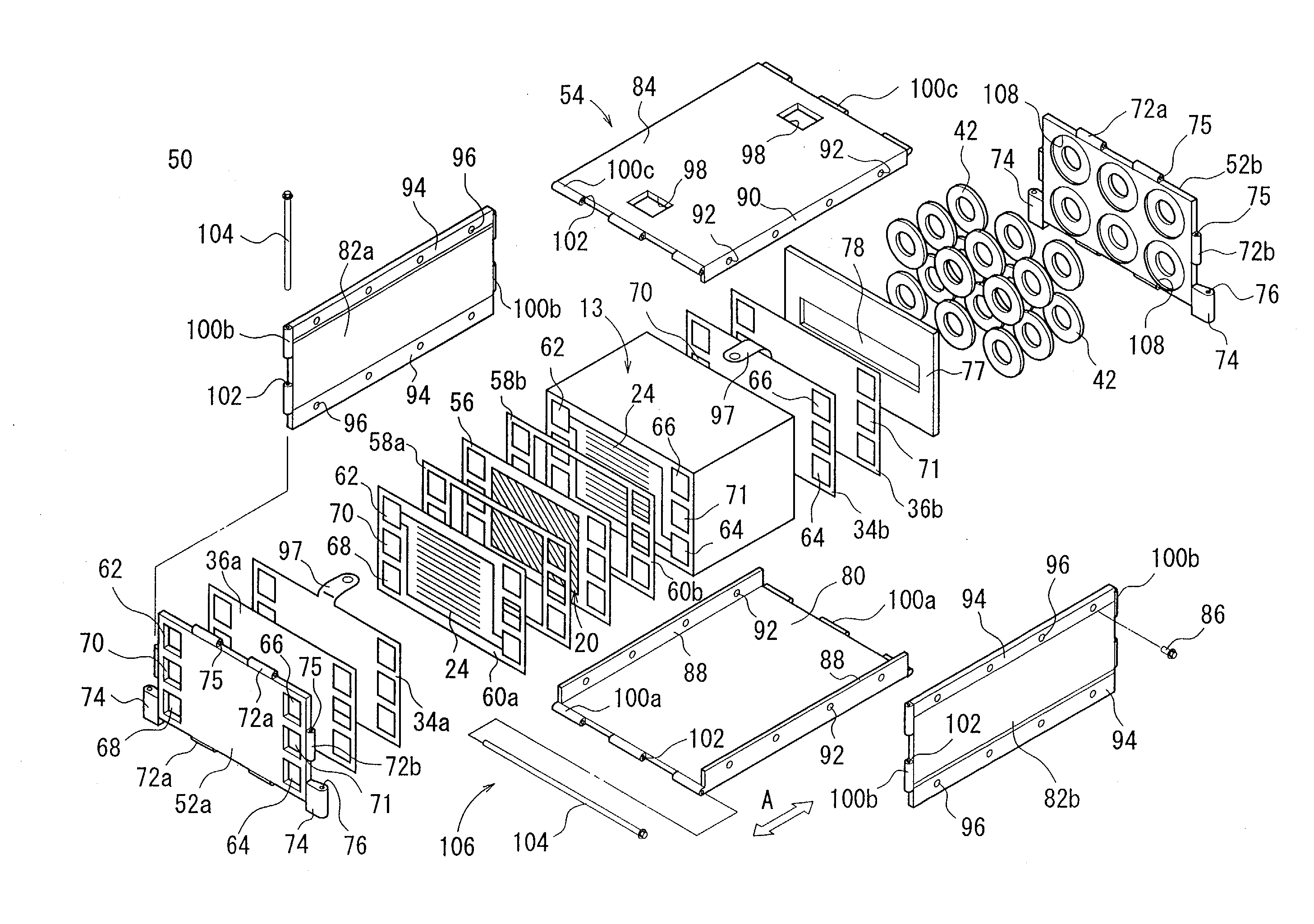
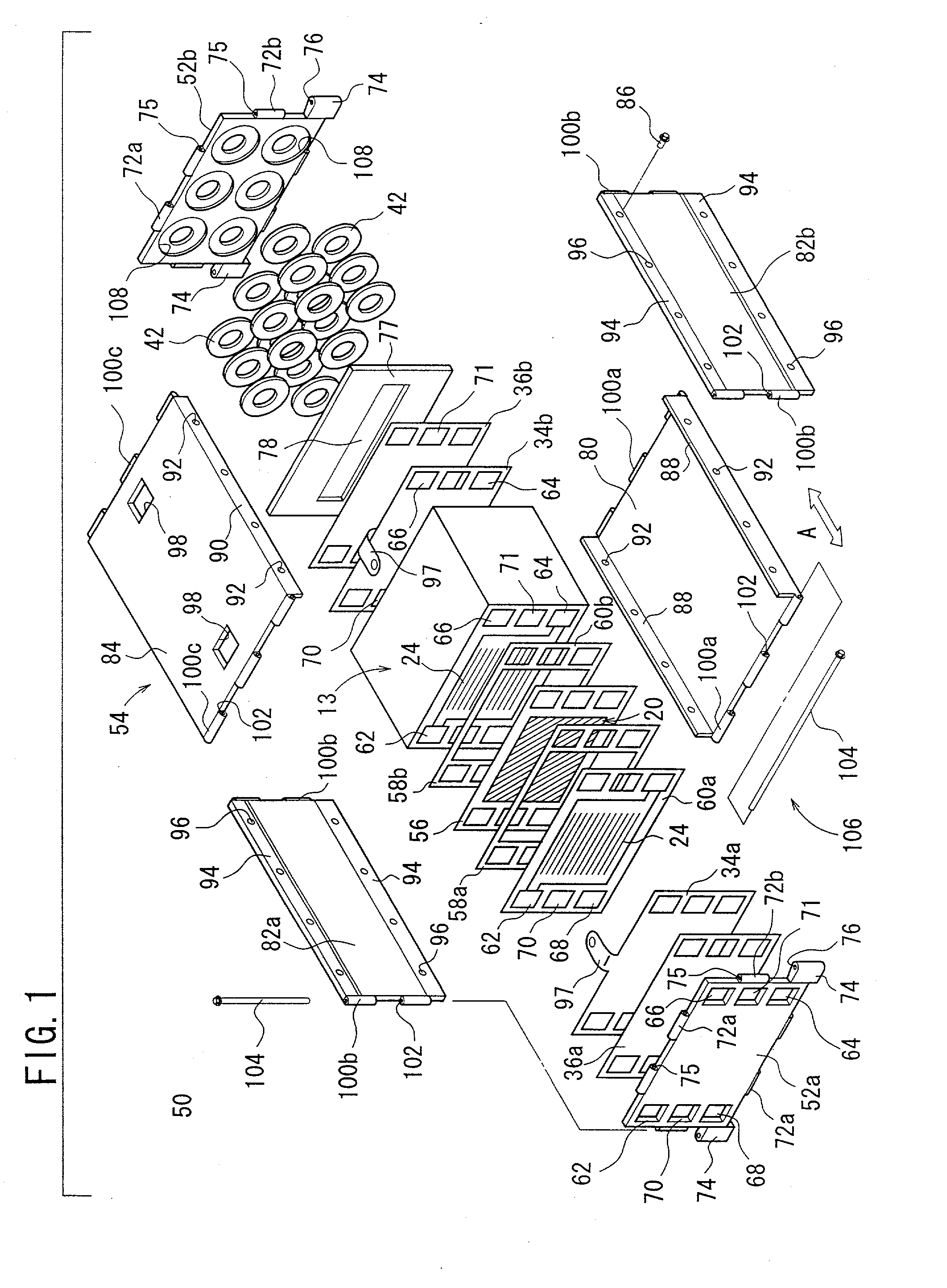
[0039] As shown in FIG. 1, the fuel cell stack 50 comprises a cell stack 13 including a plurality of cell units 12 which are stacked in the direction of the arrow A and which are electrically connected to one another in series, end plates 52a, 52b arranged outside of the cell units 12, 12 which are positioned at both ends of the cell stack 13 respectively with terminal electrodes 34a, 34b intervening therebetween, and a case 54 for accommodating the cell stack 13.

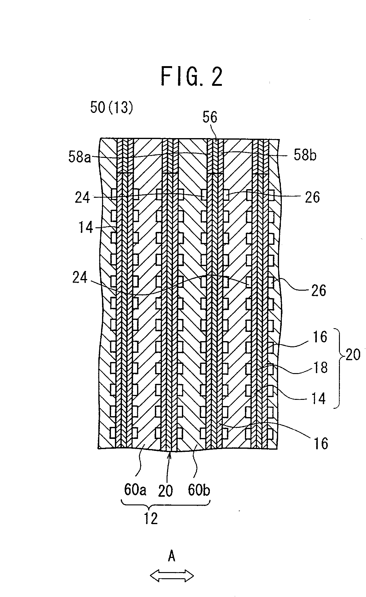
[0040] As shown in FIG. 2, the cell unit 12 has a unified body 20. The unified body 20 comprises an electrolyte layer 18 arranged between an ...


PUM

PropertyMeasurementUnit
insulatingaaaaaaaaaa
sizeaaaaaaaaaa
weightaaaaaaaaaa

Abstract

A cell stack, in which a plurality of cell units are stacked, is accommodated in a case which has a bottom plate, a first side plate, a second side plate, and a ceiling plate. End plates are arranged at both open ends of the case. The case and the end plates are connected to one another by a hinge mechanism in which pins are engaged into through-holes of tab sections to provide a fuel cell stack.

Description

BACKGROUND OF THE INVENTION[0001] 1. Field of the Invention[0002] The present invention relates to a fuel cell stack having a compact size and a light weight.[0003] 2. Description of the Related Art[0004] A magnified sectional view illustrating major parts of a general fuel cell stack is shown in FIG. 5. The fuel cell stack 10 comprises a cell stack 13 in which a plurality of cell units 12 are electrically connected to one another in series and they are stacked in the horizontal direction as shown in FIG. 5.[0005] The cell unit 12 comprises a unified body 20 which includes an electrolyte layer 18 positioned between an anode 14 and a cathode 16, and a pair of separators 22a, 22b which interpose the unified body 20 therebetween. In each of the both separators 22a, 22b, a first gas flow passage 24 for supplying and discharging the fuel gas (for example, hydrogen-containing gas containing a major component of hydrogen) with respect to the anode 14 is provided on the surface opposed to t...

Claims


Application Information

Patent Timeline
Patent Type & Authority Applications(United States)
IPC IPC(8): B60R16/04H01M8/02H01M8/24
CPCH01M8/247Y02T90/32H01M2250/20Y02T90/40Y02E60/50
Inventor KIKUCHI, HIDEAKISUGIURA, SEIJIWARIISHI, YOSHINORI
Owner HONDA MOTOR CO LTD
Why Eureka
Try Eureka