High-precision computer-aided microscope system

a computer-aided microscope and high-precision technology, applied in the field of microscopy, can solve the problems of inaccurate or imprecise microscope configurations, inability to diagnose sample specimens, and inability to accurately identify sample specimens, etc., and achieve the effect of reducing the number of manual and automatic microscope systems, and improving the accuracy of manual and automatic configurations

Inactive Publication Date: 2002-10-17
MONOGEN INC
View PDF0 Cites 17 Cited by
  • Summary
  • Abstract
  • Description
  • Claims
  • Application Information

AI Technical Summary

Benefits of technology

[0020] A principal object of the present invention is to provide a computer-aided microscope system that facilitates quick, stable and reproducible microscopic presentation of goals. Another objective of the invention is to provide a microscope having geometric accuracy in the three-motion axes. Still another object of the invention is to provide a microscope that remains stable when performing high-speed moves.

Problems solved by technology

Over the years, microscopes have evolved into very complex and sophisticated optical instruments, taking a variety of forms.
While many cancer-related cytological changes are characteristic and can be detected and classified with a high degree of accuracy by an appropriately configured microscope, inaccurate or imprecise microscope configurations can be the source of unacceptable false positive or false negative cell classifications and sample specimen diagnoses.
Unfortunately, however, traditional mechanical (e.g. fully manual) microscope systems, as well as many of the currently available automated microscope systems, have not provided the positional accuracy, repeatability, stability and resolution required for reliable, reproducible quantitative microscopic imaging applications.
However, the motorized stages in some existing automated-microscope configurations are unstable.
Consequently, these existing systems cannot rapidly, accurately, precisely and repeatedly locate and focus on diagnostically significant areas of a sample from a specimen.
Consequently, existing microscopes tend to generate yaw, pitch, roll and droop errors (i.e., introduce a third derivative, "jerk") during stage movement.
These errors are particularly troublesome in the context of automated computer-aided microscopy.
It is also problematic for human observers who also need stage motion to be dampened before they can visualize a temporally stable image.
However, in most such systems, the detector is attached only to the viewer of the microscope.
As recognized by the present inventors, this configuration thereby increases the likelihood that the camera will become unstable or misaligned during operation, potentially rendering the camera unable to capture magnified images properly.
In these systems, if the sample is illuminated with insufficient or excessive light, or with improper spectral characteristics, the detector may need to compensate for the imperfect illumination and thereby operate less than optimally.
Unfortunately, however, adjustment of these elements can be time consuming and tedious.

Method used


Image

  • High-precision computer-aided microscope system
  • High-precision computer-aided microscope system
  • High-precision computer-aided microscope system

Examples


Embodiment Construction

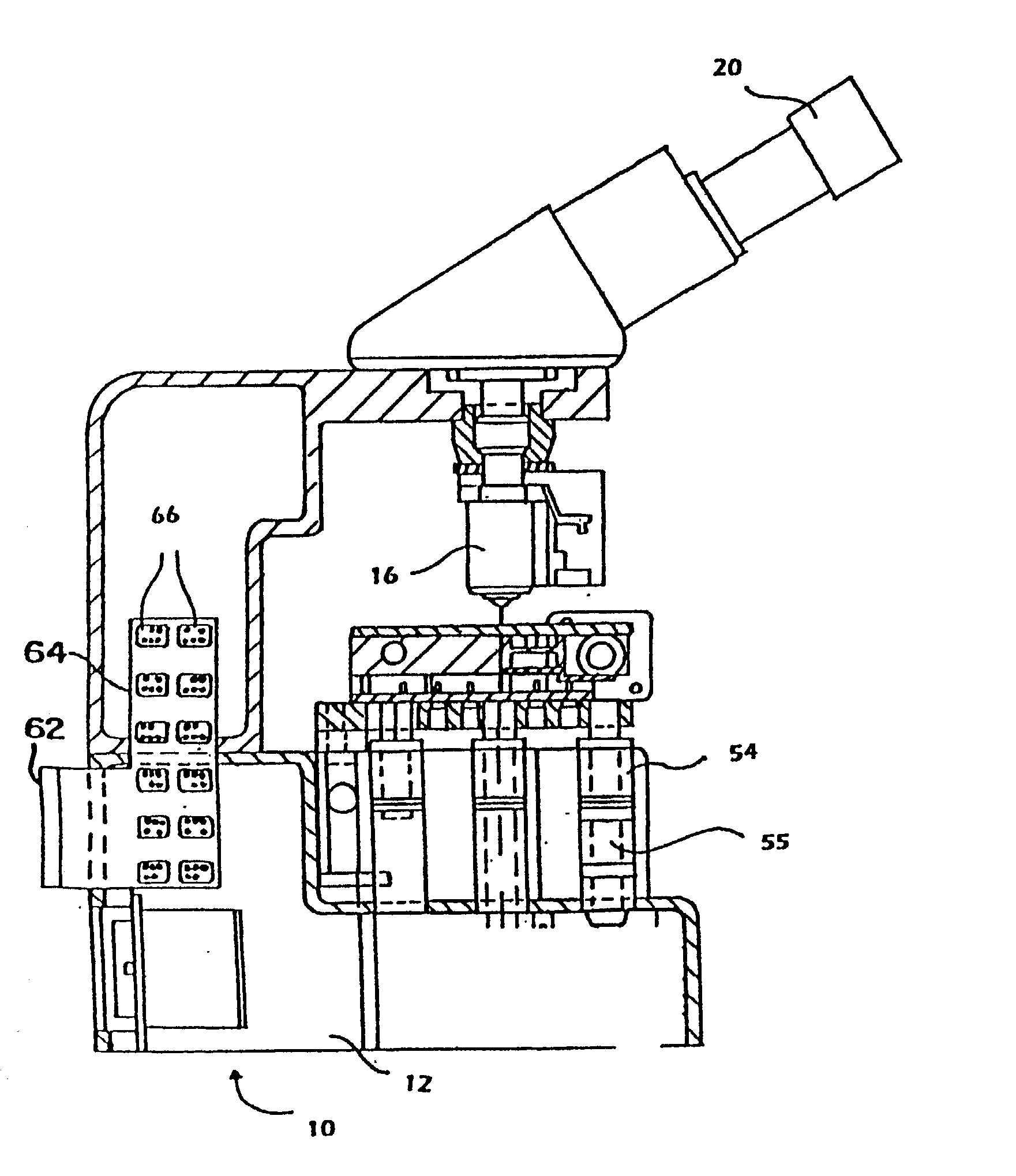
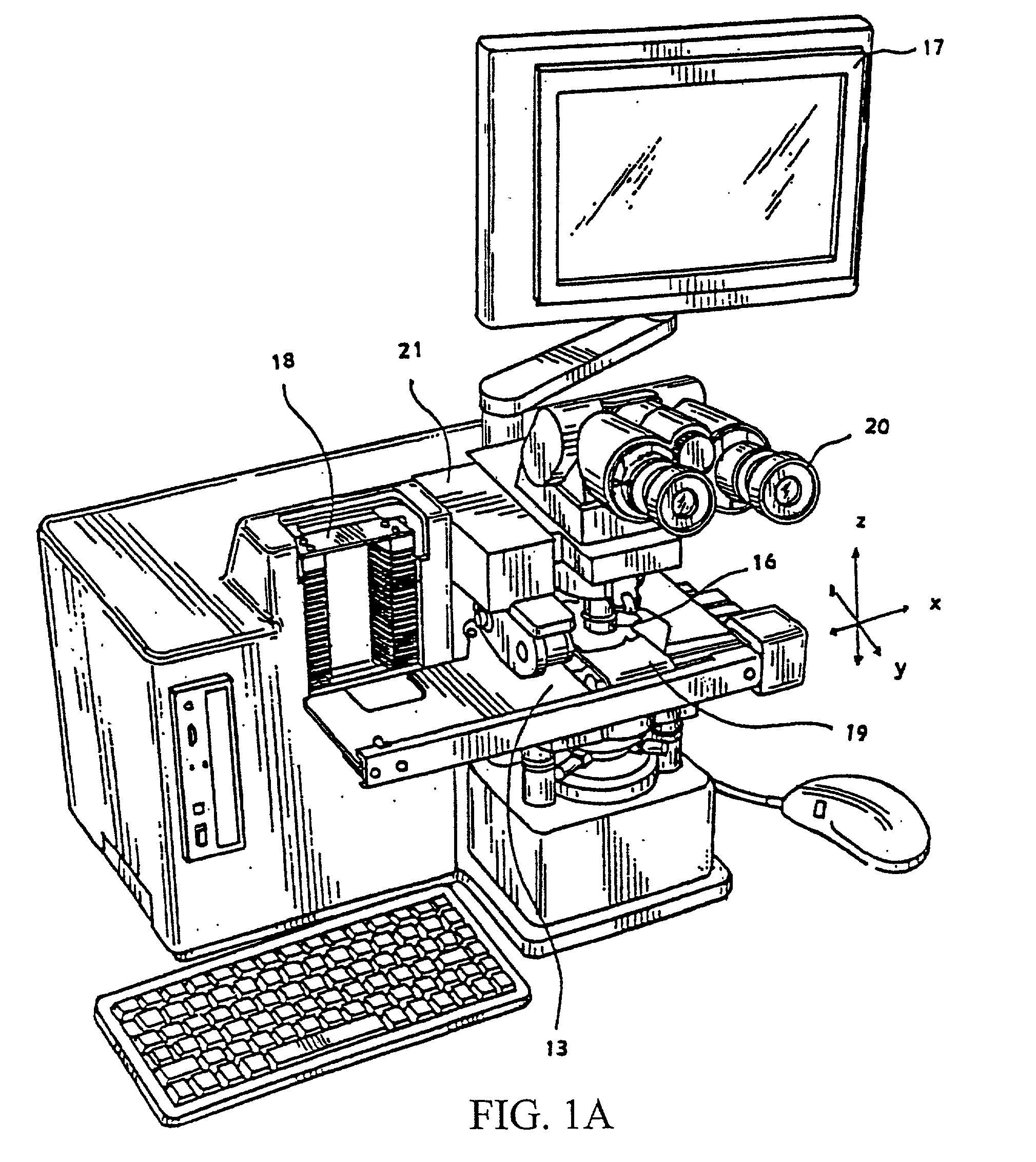
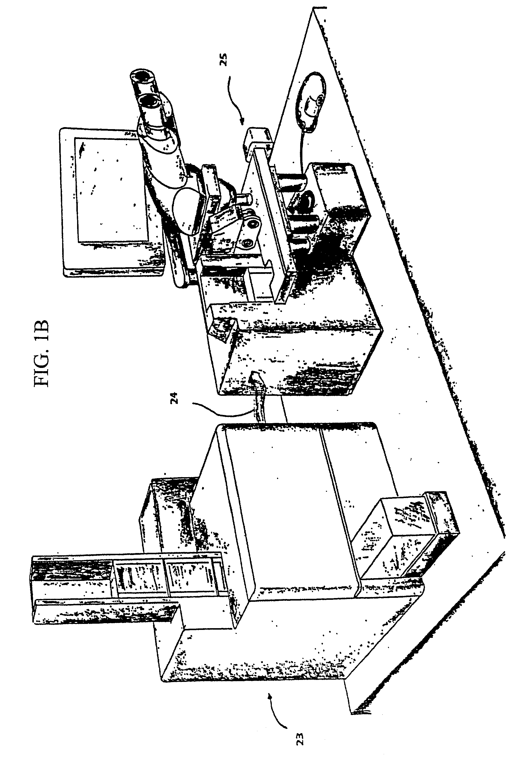
[0055] Referring to FIGS. 1-6, there is shown a schematic block diagram of a system that incorporates the principles of the invention. In particular, the Figures illustrate a system having the capability to capture images of a sample from a specimen collected from an individual and placed upon a slide, and to analyze the sample rapidly, accurately, and precisely. The microscope system may be incorporated into a variety of settings and a variety of applications.

[0056] Exemplary Applications for Microscope System

[0057] Referring to FIG. 1A, there is shown one example of a suitable configuration employing a microscope system according to the present invention. An automated video microscope having image analysis capabilities is coupled to a Data Management System (DMS). In one embodiment of the invention, the DMS comprises a conventional computer system with a processor and memory that contains patient medical history and demographic data relevant to the specimens being screened. The DM...


PUM


Abstract

A microscope frame structure having a front brace for added stability and having a dual plate structure. The front brace is rigidly coupled to the front ends of an upper portion and a base portion. The upper portion then carries optical elements such as a camera for instance. In effect, the optical elements thus reside on a bridge structure, with substantially the same structural support at both ends of the bridge. The arrangement is particularly useful in automated specimen imaging and analysis systems. The dual frame is composed of an upper plate, which supports a sample, a lower plate which contacts an elevating screw, and a spacer post in between the upper plate and lower plate. This configuration allows for more stable movement of samples.

Description

REFERENCE TO RELATED APPLICATIONS[0001] This application claims priority to U.S. Provisional Patent Application Serial No. 60 / 064,558, filed Oct. 17, 1997 and to U.S. Provisional Patent Application Serial No. 60 / 064,559, filed Oct. 20, 1997. Moreover, this application is a continuation-in-part of U.S. Patent Application Ser. No. 09 / 174,140, filed Oct. 16, 1998 and PCT Application Serial No. PCT / US98 / 21953 filed Oct. 16, 1998.[0002] 1. Field of the Invention[0003] The present invention is related generally to the field of microscopy, and more particularly to the configuration of optical microscopes and microscope-based electronic imaging systems.[0004] 2. Description of the Related Art[0005] In its most basic form, a microscope typically includes a base, a plate or stage for holding a sample, a magnifier commonly including a series of lenses, and a viewer for presenting a magnified image to an observer. The principal purpose of a microscope is to create a magnified image of a sample ...

Claims


Application Information

Patent Timeline
Patent Type & Authority Applications(United States)
IPC IPC(8): G02B21/00G02B21/08G02B21/24G02B21/36
CPCG02B21/086G02B21/362G02B21/24
Inventor MAYER, WILLIAM J.
Owner MONOGEN INC
Why Eureka
Try Eureka