Supercharge Your Innovation With Domain-Expert AI Agents!

Clip for snowmobile track

a technology for snowmobiles and tracks, applied in mechanical equipment, transportation and packaging, conveying devices, etc., can solve the problems of affecting the elastomeric material of the track, affecting the rotational speed of the track when driven, and affecting the area being damaged, so as to reduce the weight of the overall track and reduce the heat

Inactive Publication Date: 2002-10-24
CAMOPLASY INC
View PDF0 Cites 2 Cited by
  • Summary
  • Abstract
  • Description
  • Claims
  • Application Information

AI Technical Summary

Benefits of technology

[0005] The present invention is concerned with providing a metal clip which will have various effects, namely to provide lubrication for the sliding contact of the slide runner on the clip, generate a cooling effect to reduce the heat generated by such sliding contact and reduce the weight of the overall track.
[0007] The present invention therefore relates to a clip which comprises a body having an inner wall and a pair of side walls for engaging said body of said track; said inner wall including a flat face for receiving a slide runner thereon during use of said snowmobile; said flat face displaying a series of holes whereby snow or ice over which said snowmobile travels, when lodged in said holes during said use, provides lubrication for the sliding contact of the slide runner on said clip and cooling of said clip from heat generated by frictional contact of said slide runner on said clip; said holes providing weight reduction of the track thereby allowing increased rotational speed of the track.

Problems solved by technology

Great heat is generated by this frictional contact between the slide runners and the clips and this greatly affects the elastomeric material of the track.
Also, the presence of clips on a snowmobile track adds to its weight and the resulting mass has an effect on the rotational speed of the track when driven.
Also, clips are secured to the track in areas where rods are embedded transversally to reinforce the track; these areas are subject to damage.

Method used


Image

  • Clip for snowmobile track
  • Clip for snowmobile track
  • Clip for snowmobile track

Examples


Embodiment Construction

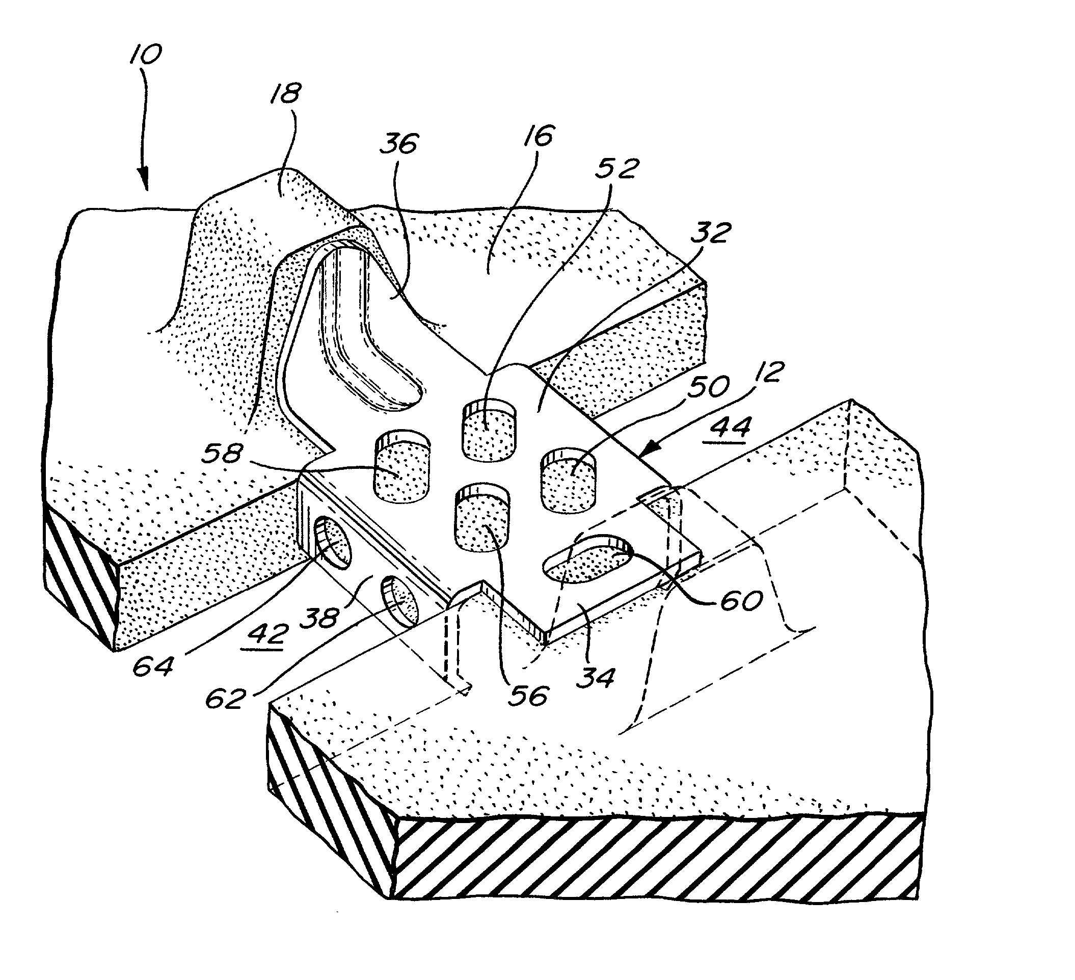
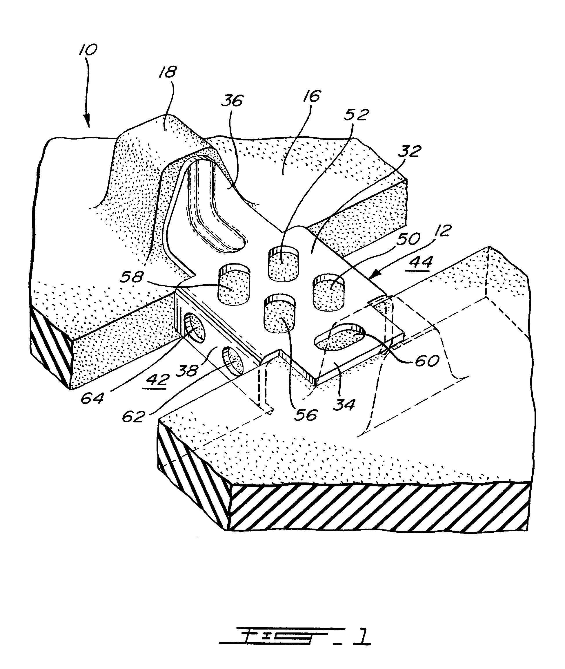
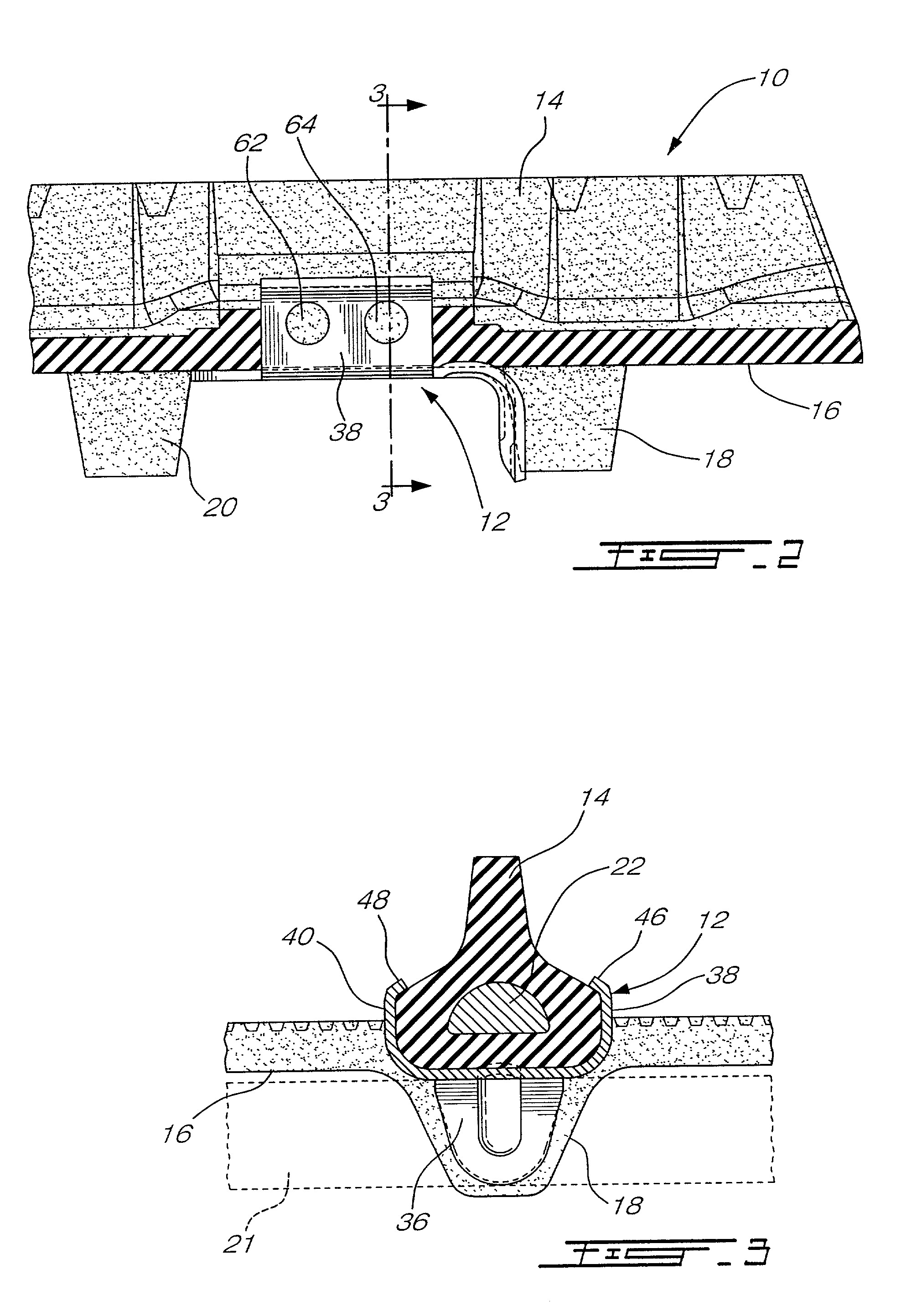
[0013] Referring to FIGS. 1-3, part of a snowmobile track, generally denoted 10, is shown equipped with a metal clip 12 made in accordance with the present invention. The track is formed of a body of elastomeric material, the outer surface of which displays a series of transverse profiles 14 that provide traction for the snowmobile as it travels over ground, especially snow or ice. The inner surface 16 of the track displays a series of integral lugs (two being shown as 18 and 20) which are contacted by sprocket wheels (not shown) that drive the snowmobile track in rotation.

[0014] Many snowmobiles have a suspension system consisting of one or more slide runners (shown in dotted lines as 21) which bear against the inner surface of the lower run of the track to maintain the track in maximum contact with the ground over which it travels. A detailed description of such a suspension system is not deemed necessary as it is well known in the art and described in many patents. It is suffice ...


PUM


Abstract

A clip for use on a track of a snowmobile of the type having a suspension system equipped with one or more elongated slide runners, the track consisting of an endless body having an outer face with transverse ground engaging profiles spaced longitudinally thereof and inner surface adapted to receive, on portions of the lower run thereof, a slide runner of the suspension system. The clip has an inner wall and a pair of side walls engaging the body of the track. The inner wall includes a flat face receiving a slide runner thereon during use of the snowmobile. The flat face displays a series of holes whereby snow or ice over which the snowmobile travels, when lodged in these holes during use, provides lubrication for the sliding contact of the slide runner on a clip and cooling of the clip body from heat generated by the frictional contact of the slide runner on the clip. Furthermore, the presence of these holes reduces the weight of the track so that this mass reduction allows higher rotational speed and less damage to reinforcing rods embedded in the track.

Description

[0001] The present invention relates to a clip for mounting to the track of a snowmobile that has a suspension system equipped with one or more elongated slide runners.[0002] Some snowmobiles are equipped with one or more slide runners as part of their suspension system. These slide runners bear on the inner surface of the lower run of the snowmobile track to provide the latter with traction and, more particularly, rest on metal clips so as to provide sliding contact with the track. Great heat is generated by this frictional contact between the slide runners and the clips and this greatly affects the elastomeric material of the track.[0003] Also, the presence of clips on a snowmobile track adds to its weight and the resulting mass has an effect on the rotational speed of the track when driven.[0004] Also, clips are secured to the track in areas where rods are embedded transversally to reinforce the track; these areas are subject to damage.OBJECTS AND STATEMENT OF THE INVENTION[0005]...

Claims


Application Information

Patent Timeline
Patent Type & Authority Applications(United States)
IPC IPC(8): B62D55/24B62D55/26
CPCB62D55/26B62D55/24
Inventor COURTEMANCHE, DENIS
Owner CAMOPLASY INC
Features
  • R&D
  • Intellectual Property
  • Life Sciences
  • Materials
  • Tech Scout
  • Unparalleled Data Quality
  • Higher Quality Content
  • 60% Fewer Hallucinations
Learn More