

Liquid-crystal display and a lighting apparatus
a liquid crystal display and lighting apparatus technology, applied in lighting and heating apparatus, identification means, instruments, etc., can solve problems such as lowering luminance and attending to loss problems
- Summary
- Abstract
- Description
- Claims
- Application Information
AI Technical Summary
Benefits of technology
Problems solved by technology
Method used
Image

Examples
first embodiment
[0061] Based on the consideration, description will be given of a reflective liquid-crystal display in the present invention by referring to FIGS. 2A, 2B, 2C, and 3.
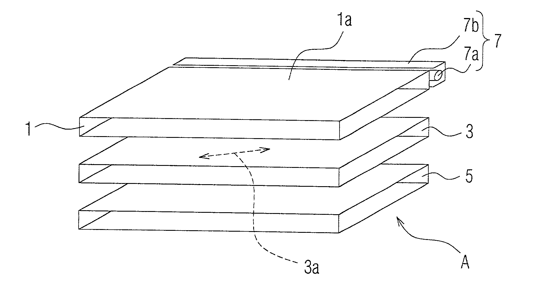
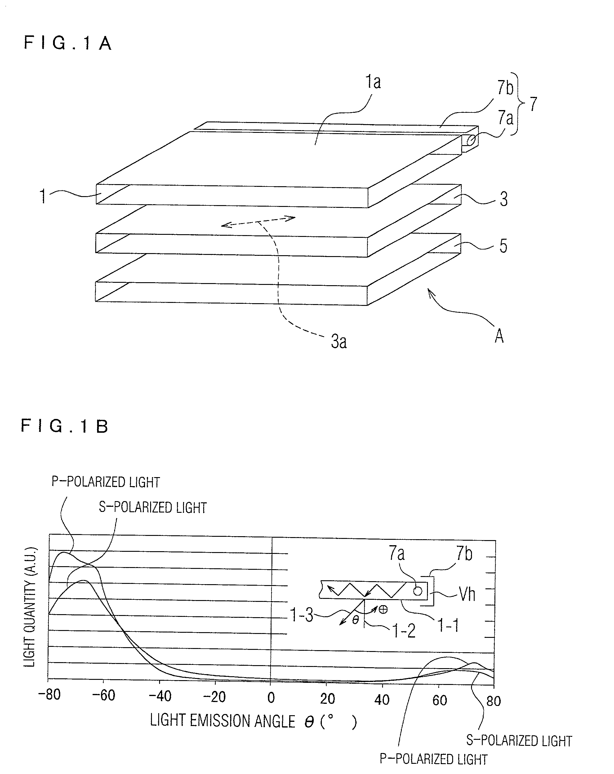
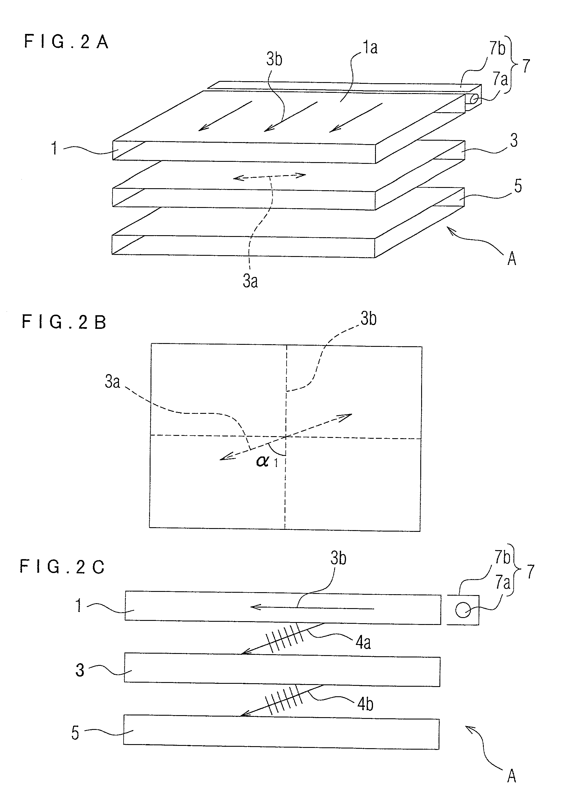
[0062] FIG. 2A is a perspective view showing an overall configuration of the reflective liquid-crystal display. FIG. 2B shows in a graph a positional relationship between an absorption axis (orthogonal to the transmission axis) of the polarizer and a projected image or a projection on the polarizer of a primary propagation direction of light incident to the polarizer when the display is viewed from above. FIG. 2C shows the configuration of the display when viewed from a side thereof. FIG. 3 is a cross-sectional view showing structure of a liquid-crystal panel.
[0063] As shown in FIG. 2A, the reflective liquid-crystal display A includes a light guiding plate 1, a polarizer 3, and a liquid-crystal panel 5 configured in this order in a downward direction. In FIG. 2A, the light guiding plate 1, the polarizer 3, and the liquid...
second embodiment
[0083] Also in the reflective liquid-crystal display B, light propagating from the polarizer 11 to the liquid-crystal panel 15 primarily includes p-polarized light, namely, light propagating in a direction similar to a direction parallel to, not vertical to, an associated surface of the polarizer 11.
[0084] The liquid-crystal panel 15 is configured in general to have reflective characteristics in which when light orthogonally enters a surface of the liquid-crystal panel 15, maximum values are obtained for its reflection factor and contrast. Therefore, it is desired that the light is incident almost orthogonally (with a small value of .theta.) to the liquid-crystal panel 15.
[0085] FIG. 5 shows an outline of relationship between an angle of incidence of light, luminance, and contrast in a reflective liquid-crystal panel. As can be seen from FIG. 5, when an angle .theta.2 of incidence of light to the liquid crystal panel (reference is made to FIG. 4C; angle relative to a normal of a sur...
third embodiment
[0139] Referring next to FIGS. 12 to 15, description will be given of a reflective liquid-crystal display in the
[0140] FIG. 12 shows an example of a general reflective liquid-crystal display. In FIG. 12, a section of a light guiding plate is almost the same in structure as that shown in FIG. 9. In FIG. 12, the same constituent components as those of FIG. 9 are assigned with reference numerals obtain by adding 30 to those used in FIG. 9, and detailed description thereof will be avoided.
[0141] The reflective liquid-crystal display 70a shown in FIG. 12 includes a polarizer 81 below the light guiding plate 73 of fine prism type and a liquid-crystal panel 85 below the polarizer 81. The liquid-crystal panel 85 includes a liquid-crystal layer, substrates (namely, a first substrate 81 and a second substrate 83) sandwiching the liquid-crystal layer, and a pixel electrode (reflective electrode) 87. The other components are almost the same as those shown in FIG. 3 and hence description thereof...
PUM
| Property | Measurement | Unit |
|---|---|---|
| alignment angle | aaaaa | aaaaa |
| alignment angle | aaaaa | aaaaa |
| alignment angle | aaaaa | aaaaa |
Abstract
Description
Claims
Application Information