
Trenching equipment

a technology of turning equipment and turning rods, which is applied in the direction of mechanical machines/dredgers, metal sawing equipment, hand-operated machines/dredgers, etc., can solve the problems of physical largeness, uneconomical, expensive, wasteful, etc., and achieves the effect of reducing the cost of operation

Inactive Publication Date: 2002-11-07
FERGUSSON GORDON MACDONEL +1
View PDF15 Cites 4 Cited by
  • Summary
  • Abstract
  • Description
  • Claims
  • Application Information

AI Technical Summary

Benefits of technology

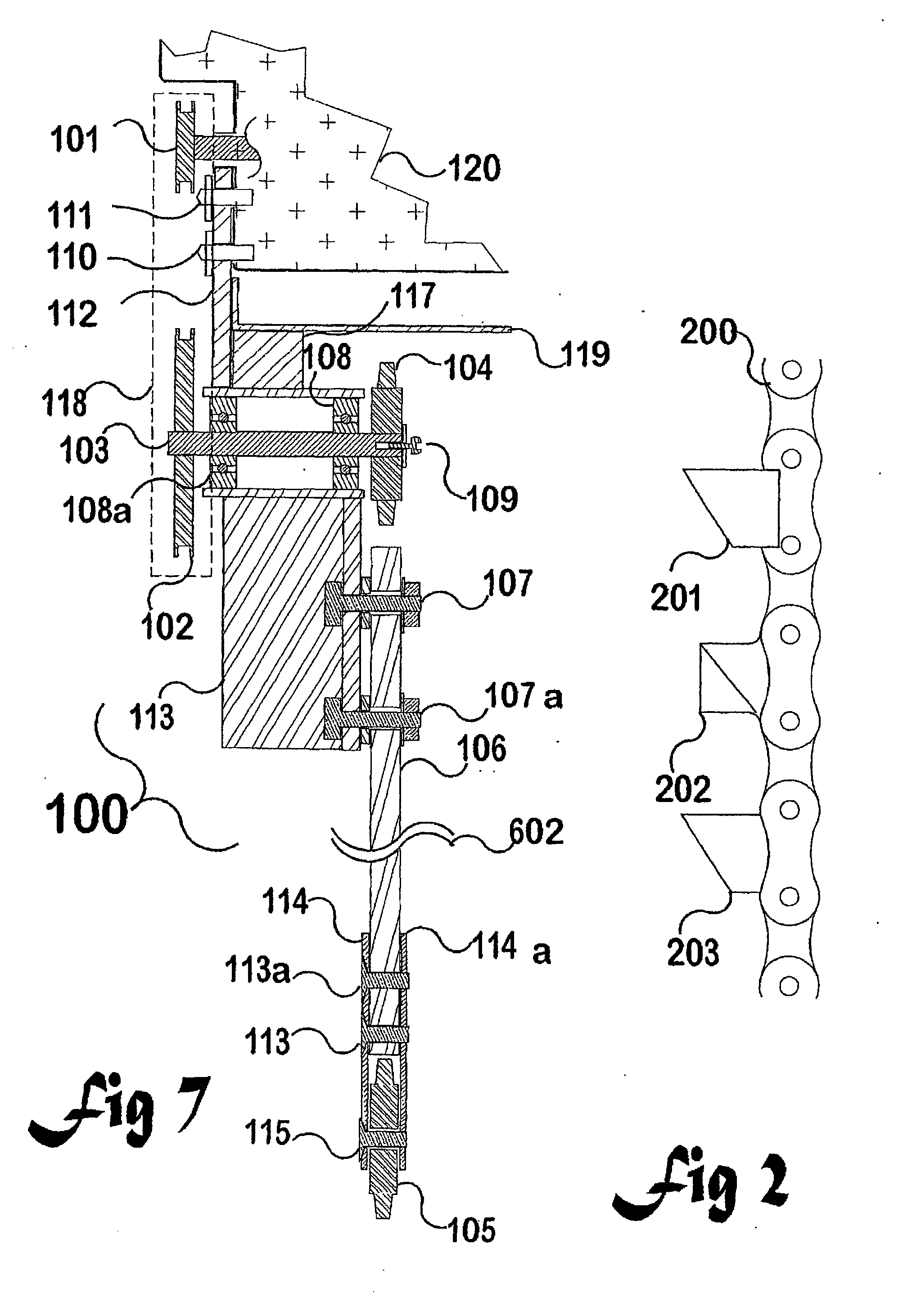
[0009] Preferably the spacing along the shaft between the driven sprocket and the primary chain receiving sprocket is sufficient to place the driven sprocket in line with the centre of gravity of the assembled chain-saw and attachment, so that in use a person holding the assembly does not experience a sideways torque caused by an unbalanced mass.
[0020] In a fourth broad aspect the attachment further includes a first guard capable of enclosing the primary chain, when in use, and a second guard capable of partially enclosing the first driven sprocket, so that when using the device a person is reasonably protected from injury and from flying debris.

Problems solved by technology

This makes them physically large, expensive, impractical, or uneconomic to own or to use for small jobs, and difficult to transport, typically requiring a second vehicle to take them from place to place.
It is wasteful to dig a trench for such a thin conduit with hand tools which are usually about 150 mm wide or more, or to use one of the previously mentioned chain or mechanical diggers.

Method used


Image

  • Trenching equipment
  • Trenching equipment
  • Trenching equipment

Examples


Embodiment Construction

[0023] The descriptions of the invention to be provided herein are given purely by way of example and are not to be taken in any way as limiting the scope or extent of the invention.

DRAWINGS

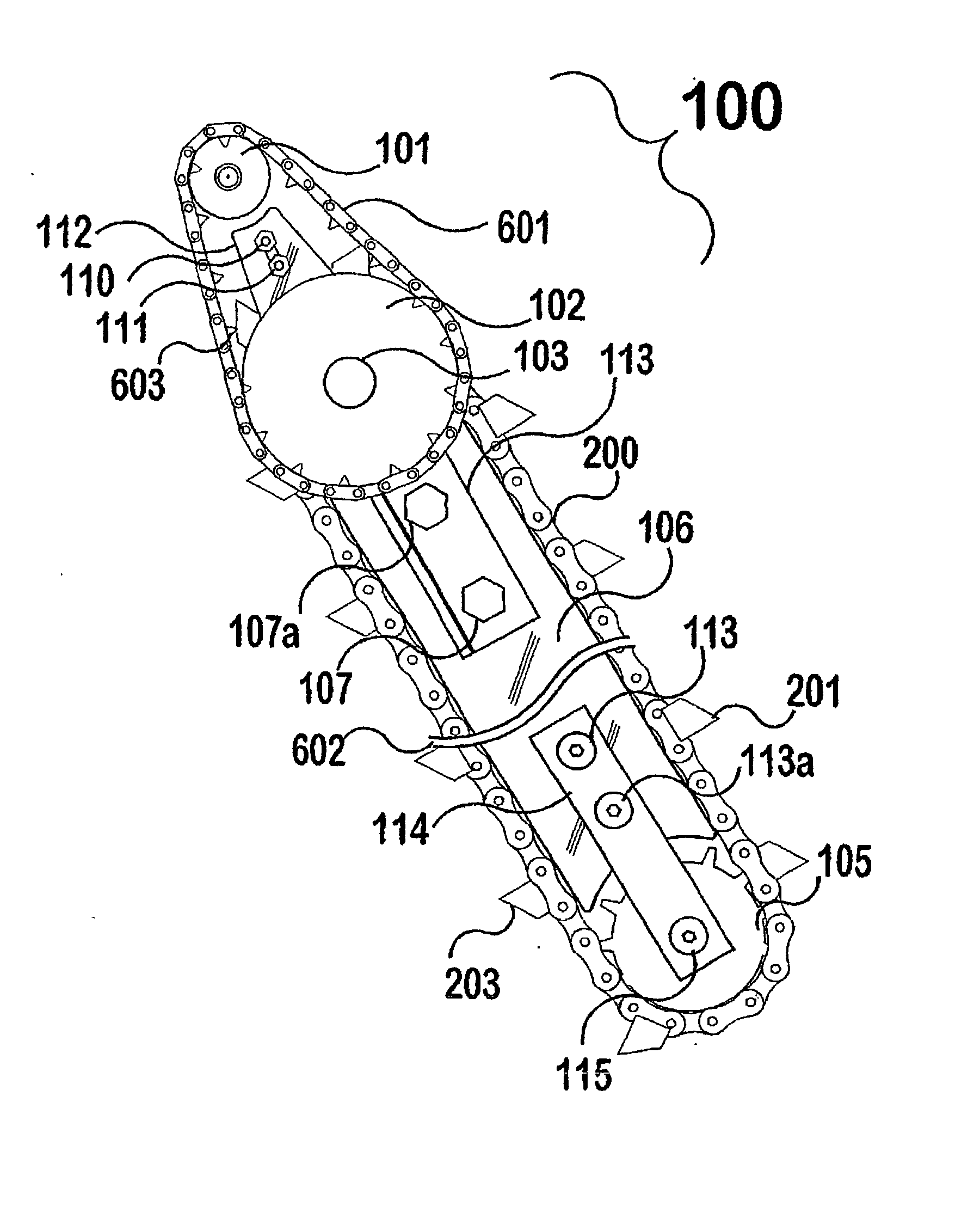
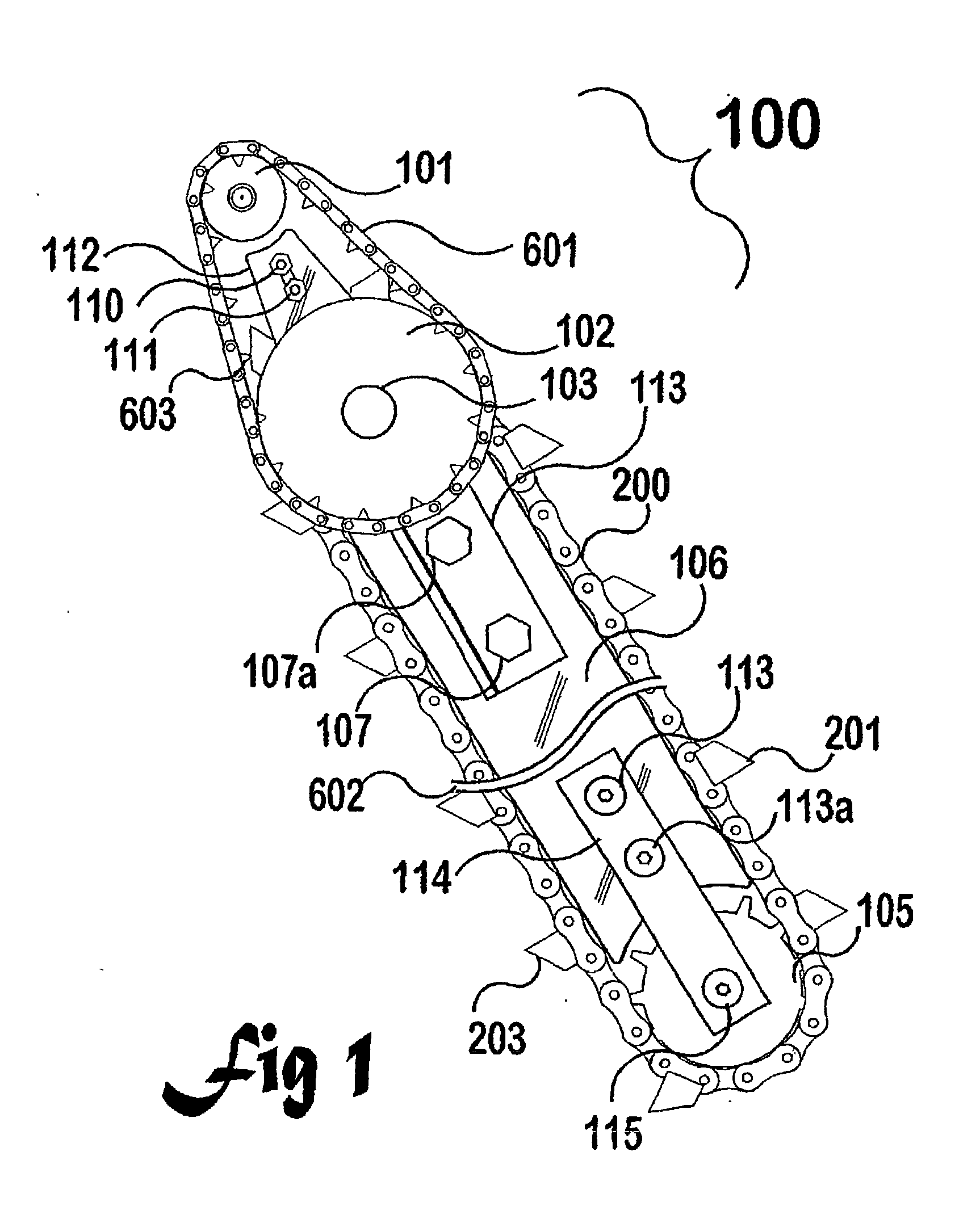
[0024] FIG. 1: is a side view of the chain-saw attachment.

[0025] FIG. 2: shows detail of a digging chain.

[0026] FIGS. 3, 4 and 5: show sections through example tooth configurations of a digging chain.

[0027] FIG. 6: shows another side of the chain-saw attachment.

[0028] FIG. 7: shows a cross-section of the chain-saw attachment.

[0029] FIG. 8: shows a skid for supporting and pulling the attachment when in use.

[0030] FIG. 9: shows a dolly for supporting and pulling the attachment when in use.

[0031] FIG. 10: shows a way to attach wheels to the attachment.

[0032] As foreshadowed in the Background, a convenient and portable digging and trenching tool capable of cutting grooves in soil about 30-35 mm wide, up to 1 metre deep and of unrestricted length is provided by the present invention. Advantages of the...


PUM

PropertyMeasurementUnit
diametersaaaaaaaaaa
diametersaaaaaaaaaa
lengthaaaaaaaaaa

Abstract

A hand-held, self-contained motor-driven trenching device (100) for cutting a slit or trench within a substrate is based on a chain-saw motor unit together with a purpose-built attachment. An unmodified chain-saw drive unit provides both motive force and a holder, although purpose-built units may employ other forms of motive power. A chain-driven reduction drive matches the chain-saw drive sprocket (101) speed to a suitable toothed digging chain cutting speed; the reduction drive being coupled to a sprocket wheel (102) aligned at one end of a sturdy, hardened steel blade (106) over which a heavy roller chain (200) bearing soil-cutting teeth (203) is pulled. The resulting trench is about 30-35 mm wide, up to 1 metre deep, and of indefinite length. The invention provides an optimised solution to a need for burying narrow cables, fibre-optic conduits, water pipes, and the like well into the ground.

Description

FIELD[0001] This invention relates to portable motorised equipment for digging a trench into the ground, particularly hand-held equipment, and includes attachments for existing hand-held power units.[0002] The power digging of holes or trenches is many times faster than manual digging with hand tools. Because of the considerable horsepower needed to drive a chain or mechanical digger, its weight and size, and the need for stable control of the digging bar or bucket, virtually all mechanical digging tools are mounted on a custom made vehicle. This makes them physically large, expensive, impractical, or uneconomic to own or to use for small jobs, and difficult to transport, typically requiring a second vehicle to take them from place to place.[0003] On many occasions about a house, a farm, or at construction sites, there is a need to bury a relatively small conduit down to perhaps 1 metre deep within the ground--typical conduit diameters being about 25 mm for examples such as telephon...

Claims


Application Information

Patent Timeline
Patent Type & Authority Applications(United States)
IPC IPC(8): B23D57/02B23D59/00B28D1/08E02F3/10E02F5/02E02F5/06
CPCB23D57/023B23D59/005E02F5/02B28D1/088E02F3/10B28D1/082
Inventor FERGUSSON, GORDON MACDONELFERGUSSON, KEITH ALEXANDER
Owner FERGUSSON GORDON MACDONEL
Learn More