Detecting tool orientation, alignment, depth, and leveling
What is Al technical title?
Al technical title is built by PatSnap Al team. It summarizes the technical point description of the patent document.
a technology of detecting tool orientation and alignment, which is applied in the direction of portable power-driven tools, metal sawing accessories, instruments, etc., can solve the problems of drill operator not knowing whether the drill is working, drilling depth, leveling, and current tools that do not provide efficient mechanisms for assisting operational accuracy
Inactive Publication Date: 2002-11-07
ROBERT BOSCH CO LTD
View PDF15 Cites 40 Cited by
Summary
Abstract
Description
Claims
Application Information
AI Technical Summary
This helps you quickly interpret patents by identifying the three key elements:
Problems solved by technology
Method used
Benefits of technology
Problems solved by technology
Current tools don't provide efficient mechanisms for aiding operational accuracy.
For example, a drill operator has no way of knowing whether the drill's bit is aligned normal to a work piece surface or the depth of a drill hole.
These same problems with alignment, depth, and leveling apply to tools other than drills.
No mechanism is provided to conveniently align or assist in the alignment of the tool.
For example, a jigsaw rotates its blade after determining that the current orientation will not yield the desired cut.
Method used
Image
Click on the blue label to locate the original text in one second.
Reading with bidirectional positioning of images and text.
Examples
Embodiment Construction
[0097] The following provides example embodiments of the above-described tool 10.
[0098] 1. Nail Gun Embodiments
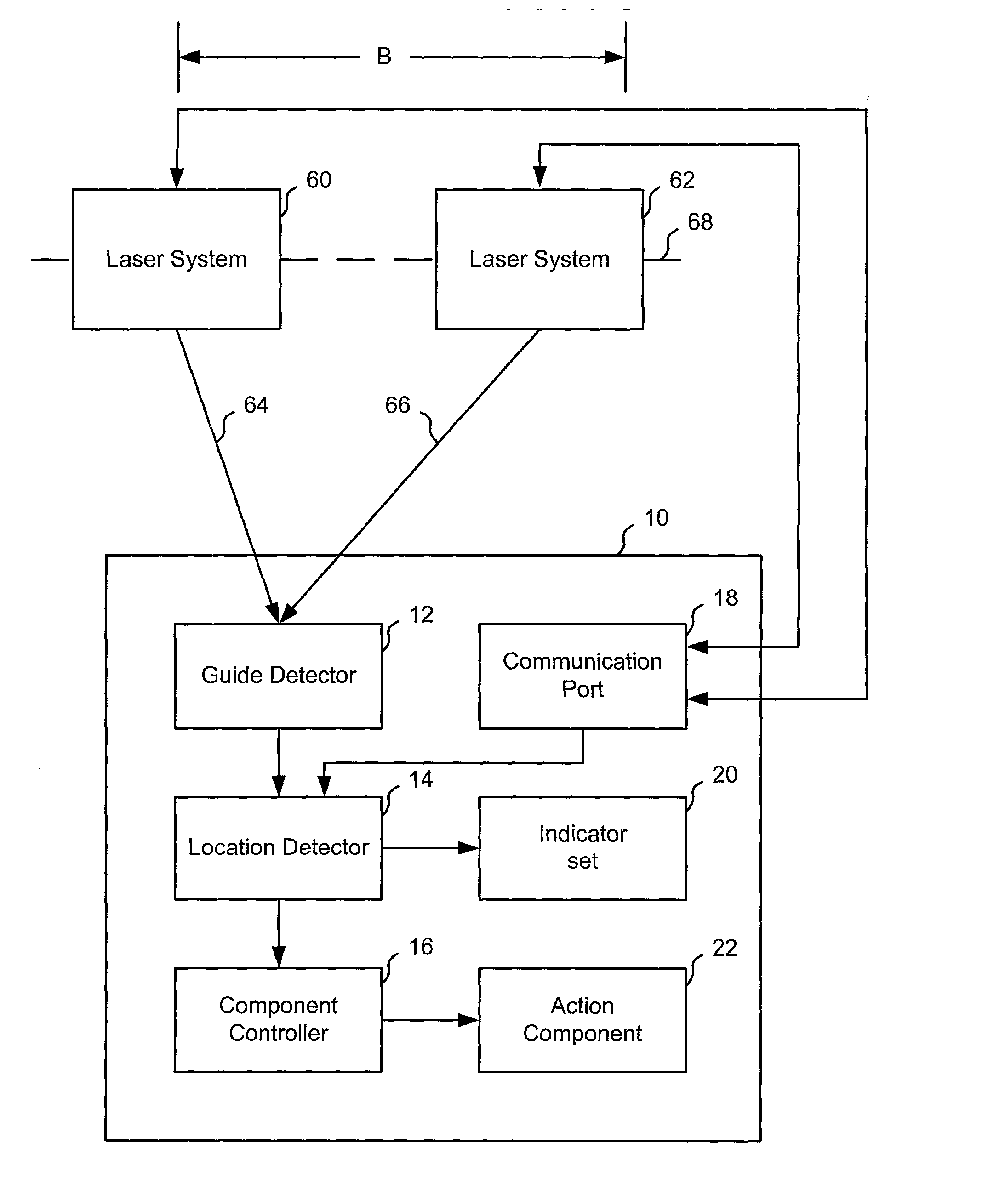
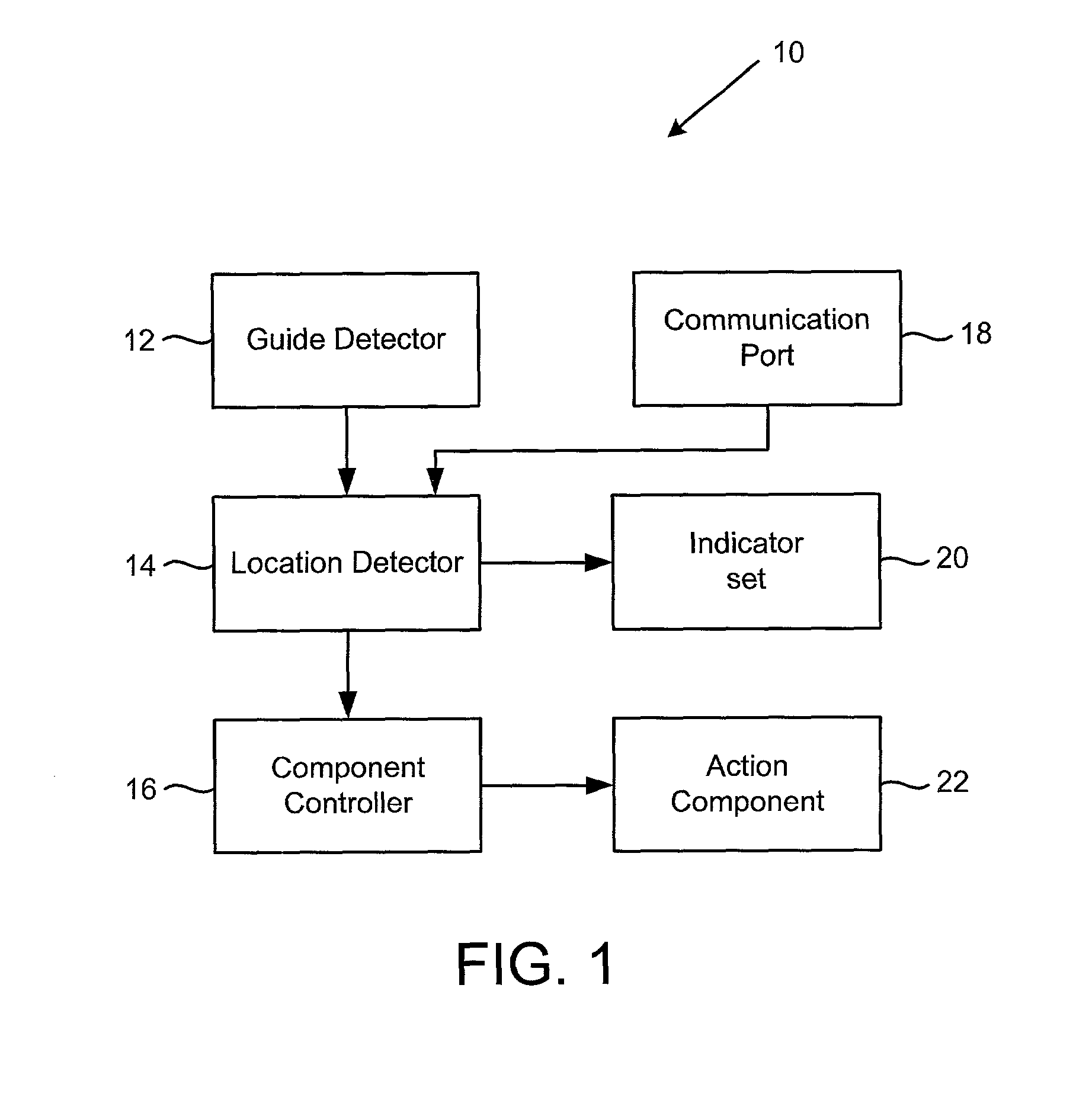
[0099] FIG. 8 shows nail gun 216 in use with laser system 212 in accordance with the present invention. Nail gun 216 has the functionality and design described above for tool 10 with reference to FIG. 3. Laser system 212 operates as described above for laser system 50 in FIG. 3. Laser system 212 provides laser beam 218 as a guide signal to nail gun 216. In the embodiment shown in FIG. 8, beam 218 reflects off mirror 220, but in alternate implementations laser beam 218 is provided directly to nail gun 216.
[0100] Photo diode detector array 214 is mounted on the head of a nail gun 216 to operate as guide detector 12. When detector array 214 has a predetermined alignment with laser beam 218 and the nail gun's trigger is squeezed, nail gun 216 automatically fires. When detector array 214 is not properly aligned with laser beam 218, nail gun 216 will not fire. This arrangement al...
PUM
Property
Measurement
Unit
angles
aaaaa
aaaaa
depth
aaaaa
aaaaa
distance
aaaaa
aaaaa
Abstract
A tool is employed in conjunction with alignment, depth, and level detectors. The tool can use all or some of these detectors. The alignment detector provides an orthogonal laser line grid on an incident surface when the detector has a predefined relationship with the surface. The depth detector emits two sets of parallel laser planes that converge with each other. When the laser planes impact on an incident surface two sets of lines are formed. The laser lines from one laser plane set move closer to the lines from the other laser plane set as the depth detector moves closer to the surface-showing changes in depth or distance. The level detector employs two converging laser planes. An operator positions the level detector above an incident surface, so the laser planes' line of intersection appears on the surface if the surface is level. If the surface is not level, lines separate from each laser plane appear on the surface-signaling the need for a level adjustment. Some versions of the tool have the ability to detect their own orientation and make adjustments based on the orientation. Example tools include nail guns, jigsaws, circular saws, routers, and drills.
Description
CLAIM OF PRIORITY[0001] This application claims the benefit of U.S. Provisional Application No. 60 / 270,733, "Manually Guided, Self-Correcting, Power Tools," filed on Feb. 22, 2001, and U.S. Provisional Application No. 60 / 271,844, "Manually Guided, Self-Correcting, Power Tools," filed on Feb. 27, 2001, both of which are incorporated herein by reference.[0002] This Application is related to the following Application:[0003] "Tools With Orientation Detection," by Andrew Butler, Christopher A. Tacklind, Lance Reisman, Aragon Burlingham, Dan Adams, Gene Duval, William Scott, Rick Feffer, and Jon Carver, Attorney Docket No. TOOLZ-01056US2, filed the same day as the present application, and incorporated herein by reference.[0004] 1. Field of the Invention[0005] The present invention is directed to detecting tool orientation, alignment, depth, and leveling.[0006] 2. Description of the Related Art[0007] Tool operators often need to perform precise operations with their tools. Examples of such...
Claims
Application Information
Patent Timeline
Application Date:The date an application was filed.
Publication Date:The date a patent or application was officially published.
First Publication Date:The earliest publication date of a patent with the same application number.
Issue Date:Publication date of the patent grant document.
PCT Entry Date:The Entry date of PCT National Phase.
Estimated Expiry Date:The statutory expiry date of a patent right according to the Patent Law, and it is the longest term of protection that the patent right can achieve without the termination of the patent right due to other reasons(Term extension factor has been taken into account ).
Invalid Date:Actual expiry date is based on effective date or publication date of legal transaction data of invalid patent.
Patent Type & Authority Applications(United States)
Inventor BUTLER, ANDREW G.TACKLIND, CHRISTOPHER A.REISMAN, LANCEBURLINGHAM, ARAGONADAMS, DANIEL T.DUVAL, EUGENE F.SCOTT, WILLIAM A.FEFFER, RICKCARVER, JONATHAN