Footing for sound-barrier walls

Inactive Publication Date: 2002-11-14
CONCRETE PRECAST SYST
View PDF0 Cites 26 Cited by
  • Summary
  • Abstract
  • Description
  • Claims
  • Application Information

AI Technical Summary

Benefits of technology

0014] In this manner, the sound-barrier wall can be manufac

Problems solved by technology

As is well known, sound-barrier walls can be very expensive, especially if a wall is very long.
Accordingly, cost is a major concern to both manufacturers and purchasers of such walls.
However, cost reduction cannot be achieved to the detriment of effectiveness and cer

Method used


Image

  • Footing for sound-barrier walls
  • Footing for sound-barrier walls
  • Footing for sound-barrier walls

Examples


Embodiment Construction

[0031] Other objects, features and advantages of the invention will become apparent from a consideration of the following detailed description and the accompanying drawings.

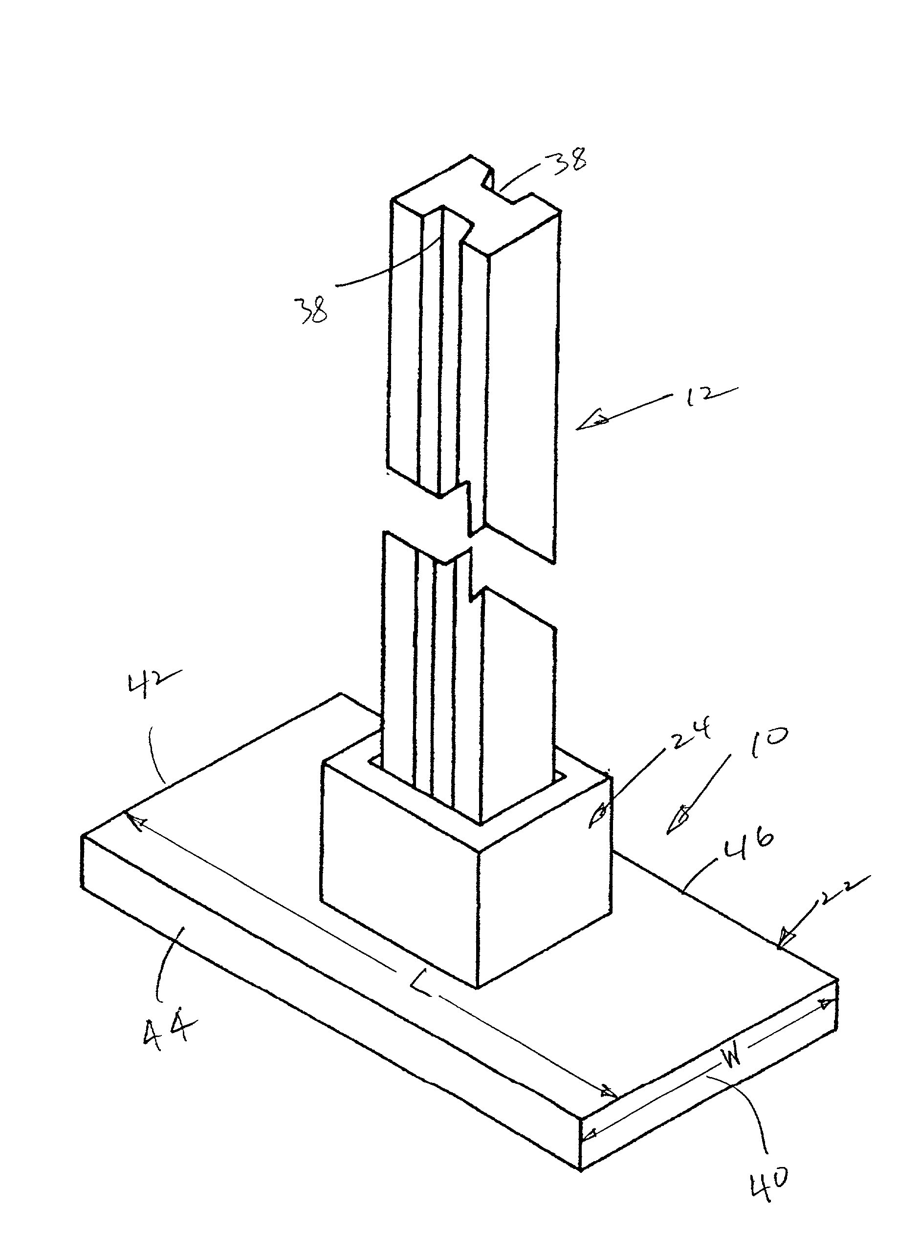
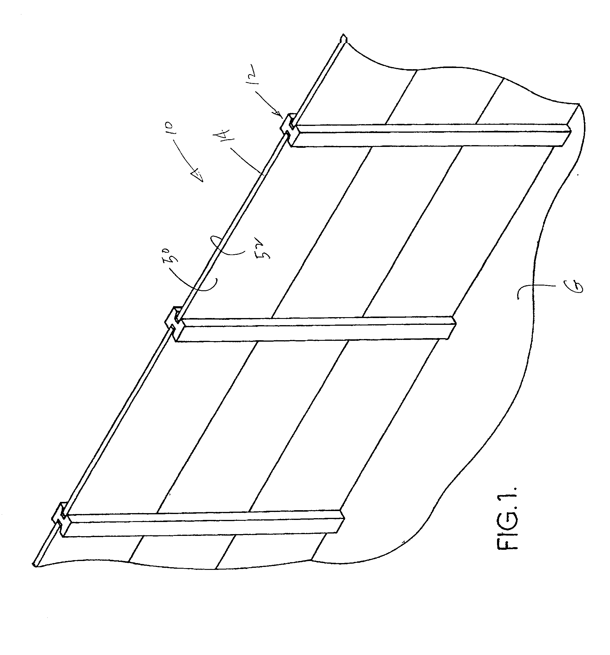
[0032] Shown in FIG. 1 is a sound-barrier wall 10 which is positioned adjacent to a roadway (not shown) to control noise generated at the roadway. Wall 10 is mounted in the ground G which can be uneven, or difficult to work in as is well known to those skilled in the art. Wall 10 generally includes stanchions 12 anchored in ground G to extend upwardly from the ground and which support sound-controlling panels, such as panel 14. Panels 14 can be formed in the manner described in the referenced patents; therefore, no discussion will be presented regarding the panels per se.

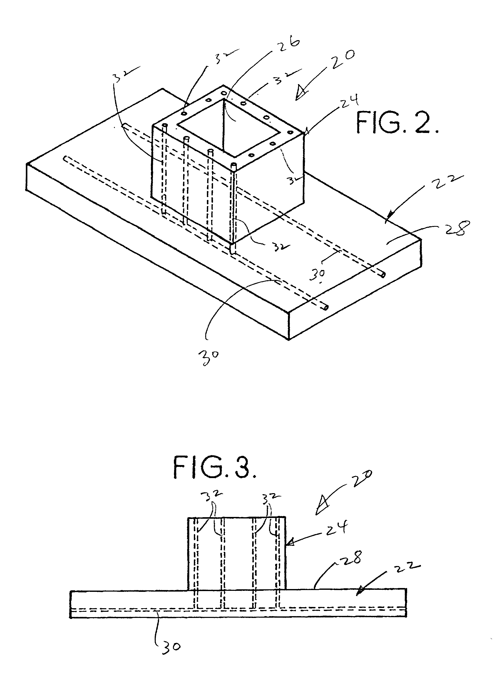
[0033] As discussed above, placing stanchions 12 in the ground can be a difficult process, especially if the ground is uneven or rocky. Accordingly, the present invention is directed to a footing that can be used in an effective and efficient man...


PUM


Abstract

A footing for use to support stanchions of sound-barrier walls is a one-piece monolithic element that includes a base having a plurality of prestressing cables therein. A stanchion is accommodated in a bore defined in either a sleeve included with the base or directly in the base. If a sleeve is included, the sleeve includes a plurality of prestressing strands or rebars. One form of sound-barrier wall includes adjacent panels on opposite sides of a stanchion whereby a panel must be lifted in order to tip the stanchion over so wind forces are safely accommodated. Another form of the footing includes projections that extend into the bore. Various forms of sound-barrier wall configurations can be accommodated by the footing.

Description

[0001] The present invention relates to the general art of static structures, and to the particular field of static structures with an exposed configuration and having an acoustical function and support elements therefor.[0002] As discussed in the inventor's prior patents, U.S. Pat. Nos. 5,564,241 and 5,678,363, the disclosures of which are incorporated herein by reference, noise associated with roadways is a serious concern. Accordingly, the art includes examples of many sound-barrier walls which are designed to maintain noise levels adjacent to roadways at acceptable levels. The referenced patents represent the inventor's design, and those skilled in the art will know of others.[0003] As is well known, sound-barrier walls can be very expensive, especially if a wall is very long. Accordingly, cost is a major concern to both manufacturers and purchasers of such walls. Due to the size of most projects, anything that can be done to reduce costs can have great benefits. However, cost r...

Claims


Application Information

Patent Timeline
IPC IPC(8): E01F8/00E02D27/42
CPCE02D27/42E01F8/0023
Inventor OGORCHOCK, PAUL
Owner CONCRETE PRECAST SYST
Why Eureka
Try Eureka