
Adaptive method and apparatus for transmission line analysis

a transmission line and adaptive technology, applied in the field of communication, can solve the problems of lowering the cost of dispatching, reflection or echo, and expensive dispatching of service technicians

Inactive Publication Date: 2002-11-14
MACOM TECH SOLUTIONS HLDG INC
View PDF12 Cites 70 Cited by
  • Summary
  • Abstract
  • Description
  • Claims
  • Application Information

AI Technical Summary

Problems solved by technology

The dispatch of service technicians is expensive and hence, the less time the service technician must spend locating the line anomaly, the lower the cost of the dispatch.
Impedance irregularities in the line cause a reflection or echo when encountered by the pulse.
One disadvantage arises as a result of the necessary, but undesirable, use of a high power pulse.
Transmission of a high power pulse on a line disrupts communication and operation of the other pairs in the binder by creating crosstalk between pairs.
Another disadvantage of this prior art method arises because of the available echo processing methods.
This limits a system's ability to detect weak return echoes which translate into a limitation on the ability of prior art pulse system to accurately analyze the distant end of a long line.
Yet another drawback associated with the prior art method of high power pulse reflection analysis is the limited platforms available to generate a high power pulse.
As a result, pulse test equipment must be implemented as a separate piece of test equipment and may not be an integrated circuit.
This increases the cost of testing by requiring a separate piece of test equipment and can make its use inconvenient.
If `e` is too large, the correlation process will result in a side lobe.

Method used


Image

  • Adaptive method and apparatus for transmission line analysis
  • Adaptive method and apparatus for transmission line analysis
  • Adaptive method and apparatus for transmission line analysis

Examples


Embodiment Construction

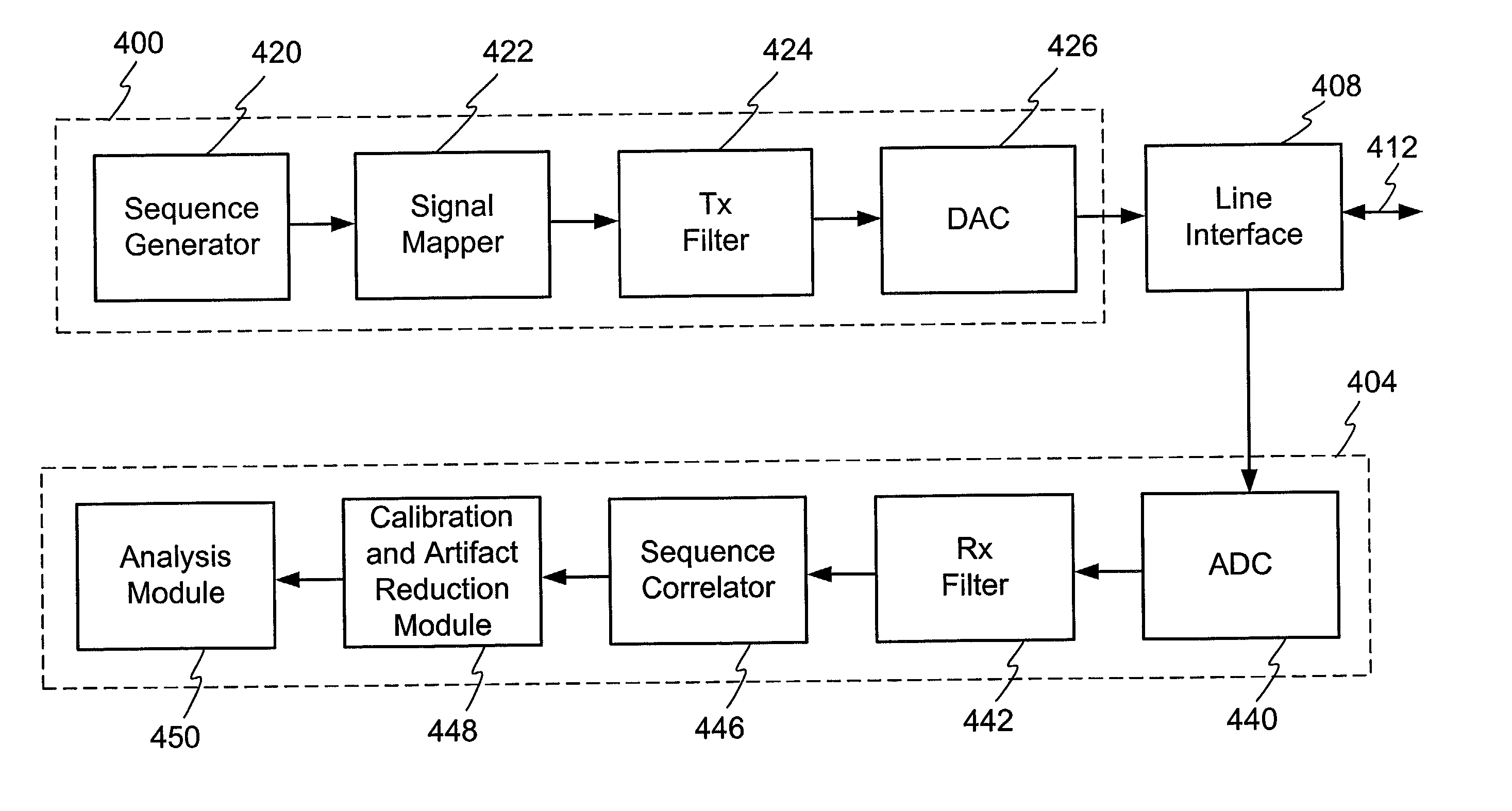
[0091] FIG. 4 illustrates a more detailed block diagram of an example embodiment of one configuration of the invention. Broadly, the elements of FIG. 4 includes a transmit module 400 and a receive module 404. Connecting the transmit module 400 and the receive module 404 is a line interface 408 and other possible logic and lines (not shown). The line interface 408 connects the transmit module 400 and the receive module 404 to a communication channel 412. The line interface 412 includes apparatus to separate or filter the transmitted signal from the received signal and attempts to impedance match the transmit module 400 to the channel 412 and the receive module 404 to the channel. In one embodiment, the line interface 408 comprises a hybrid. The line interface 408 may also be configured to interface a single conductor of the transmit module 400 or the receive module 404 to twisted pair conductors. Although designed to reduce impedance mismatch, the line interface 412 often creates som...


PUM


Abstract

A method and system for performing sequence time domain reflectometry to determine the location of line anomalies in a communication channel is disclosed. In one embodiment, the system generates a sequence signal and transmits the sequence signal over a channel. The system receives one or more reflection signals, and performs reflection signal processing on the reflection. In one embodiment, the reflection signal is correlated with the original sequence signal to generate a correlated signal. The system determines a time value between the start of the reflection signal and the subsequent points of correlation to determine a location of a line anomaly. In one embodiment preprocessing and post-processing occurs to counter the effects of a communication device, such as a DMT modulator / demodulator. In one embodiment sampling of the sequence and reflection signal may occur at different times or at a different phase to provide greater resolution of the line anomaly location.

Description

[0001] The following application is a continuation-in-part of the U.S. patent application having Ser. No. 09 / 810,932, which was filed on Mar. 16, 2001.1. FIELD OF THE INVENTION[0002] This invention relates generally to communications and in particular to a system and method for analyzing a transmission line.2. RELATED ART[0003] Historically, new communication technologies are continually being introduced to improve the ease and rate at which data can be exchanged between remote locations. One factor that must be considered when communicating electronic data is the medium over which the data will travel. This is often referred to as determining the channel quality, line characteristics, line transfer function, insertion loss, or channel impulse response. Numerous different types of conductors are utilized to conduct communication signals. One example medium that is commonly installed throughout the world is twisted pair conductors as are traditionally used to provide telephone servic...

Claims


Application Information

Patent Timeline
Patent Type & Authority Applications(United States)
IPC IPC(8): G01R31/02G01R31/11H04B3/46H04L12/26
CPCG01R31/021G01R31/11H04B3/493H04L43/50Y04S40/168H04L12/2697G01R31/58Y04S40/00
Inventor JONES, KEITH R.TREVINO, GILBERTO ISAAC SADAJONES, WILLIAM W.JONSSON, RAGNAR H.
Owner MACOM TECH SOLUTIONS HLDG INC
Learn More