
Pressure-controlled three-way valve device for transport vehicle tires and remote pressure control method

a technology of transportation vehicle tires and pressure control methods, which is applied in the direction of functional valve types, process and machine control, instruments, etc., can solve problems such as cumbersome installation

Inactive Publication Date: 2002-11-21
COL VEN
View PDF0 Cites 24 Cited by
  • Summary
  • Abstract
  • Description
  • Claims
  • Application Information

AI Technical Summary

Benefits of technology

[0014] Yet a further object of the invention is a valve device of a simple yet sturdy construction, such that it is not too expensive considering the number of like devices a multi-axle vehicle needs and that the location (on the wheel) of installation of each, respectively, difficult to protect against strikes and jerks and, therefore, exposed to mechanical accidents, for example by stones picked up the same or another vehicle.
[0019] In a more preferred embodiment, to improve reliability and operation speed of the valve device, the average initial friction of the O-ring is compensated by adding a second spring or equivalent elastic means to provide a threshold force urging of the plunger towards the inlet valve having a piston or closing means moveably seated on the plunger. This spring is in opposition to the first spring urging the inlet valve against the plunger and is dimensioned to yield to the force of the latter absent enough air pressure at the inlet port and, at the same time, urge the plunger to recover faster in response to a control pressure signal at the inlet port.
[0020] In an even more preferred embodiment, respective filters are arranged in both ports to protect the valve components from dust and dirt entering eventually via the ports and coming from the inflater system and the tire. These filters may be placed in these ports for seating the springs respectively urging the piston and the plunger.

Problems solved by technology

To this end, a conventional 3-way valve, such as a solenoide for example, would not the best choice for the component identified by reference number 39 therein, to avoid having to lay out control lines to the position of the wheels which make the installation cumbersome apart from being difficult to protect against mechanical accidents.

Method used


Image

  • Pressure-controlled three-way valve device for transport vehicle tires and remote pressure control method
  • Pressure-controlled three-way valve device for transport vehicle tires and remote pressure control method
  • Pressure-controlled three-way valve device for transport vehicle tires and remote pressure control method

Examples


Embodiment Construction

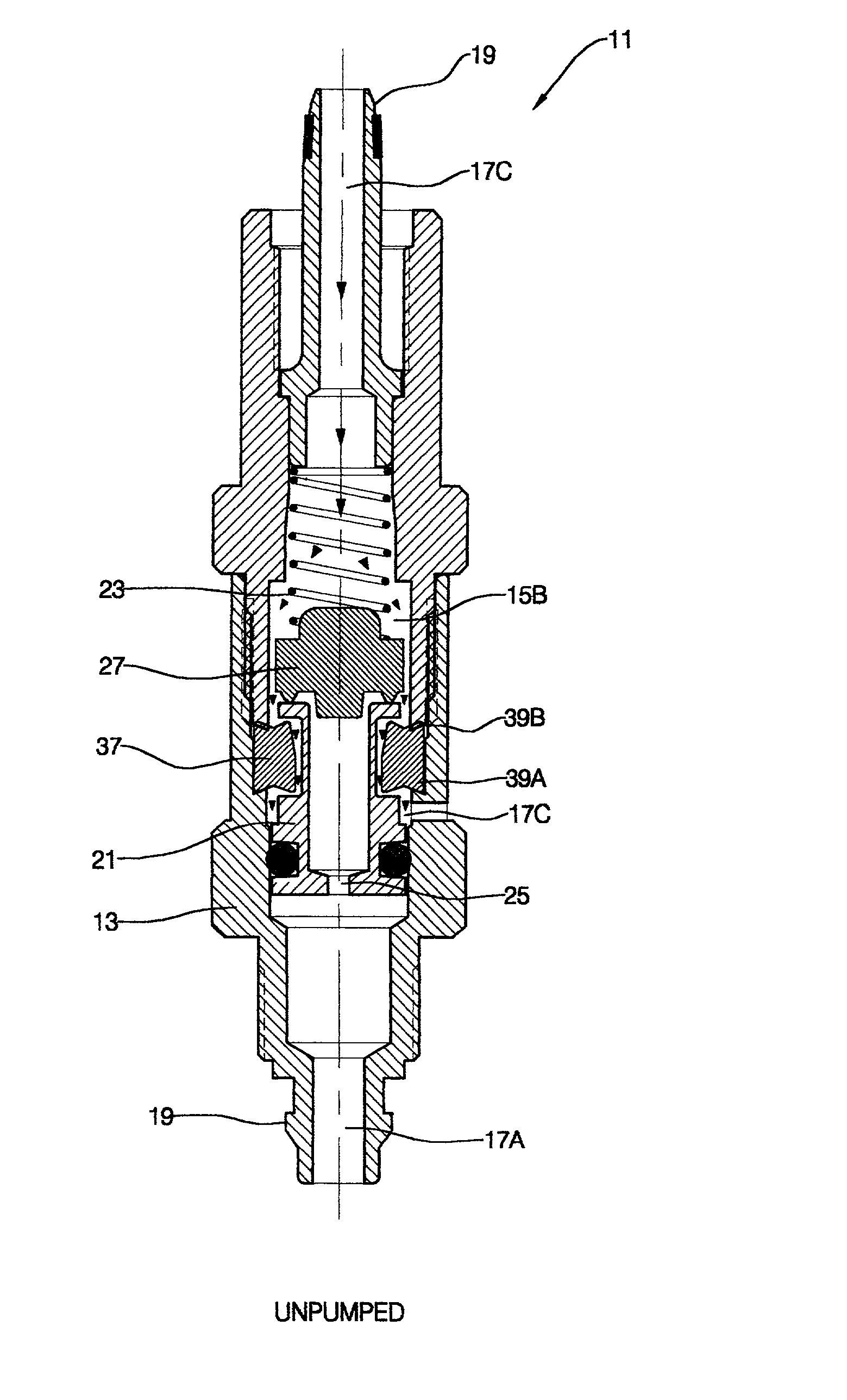
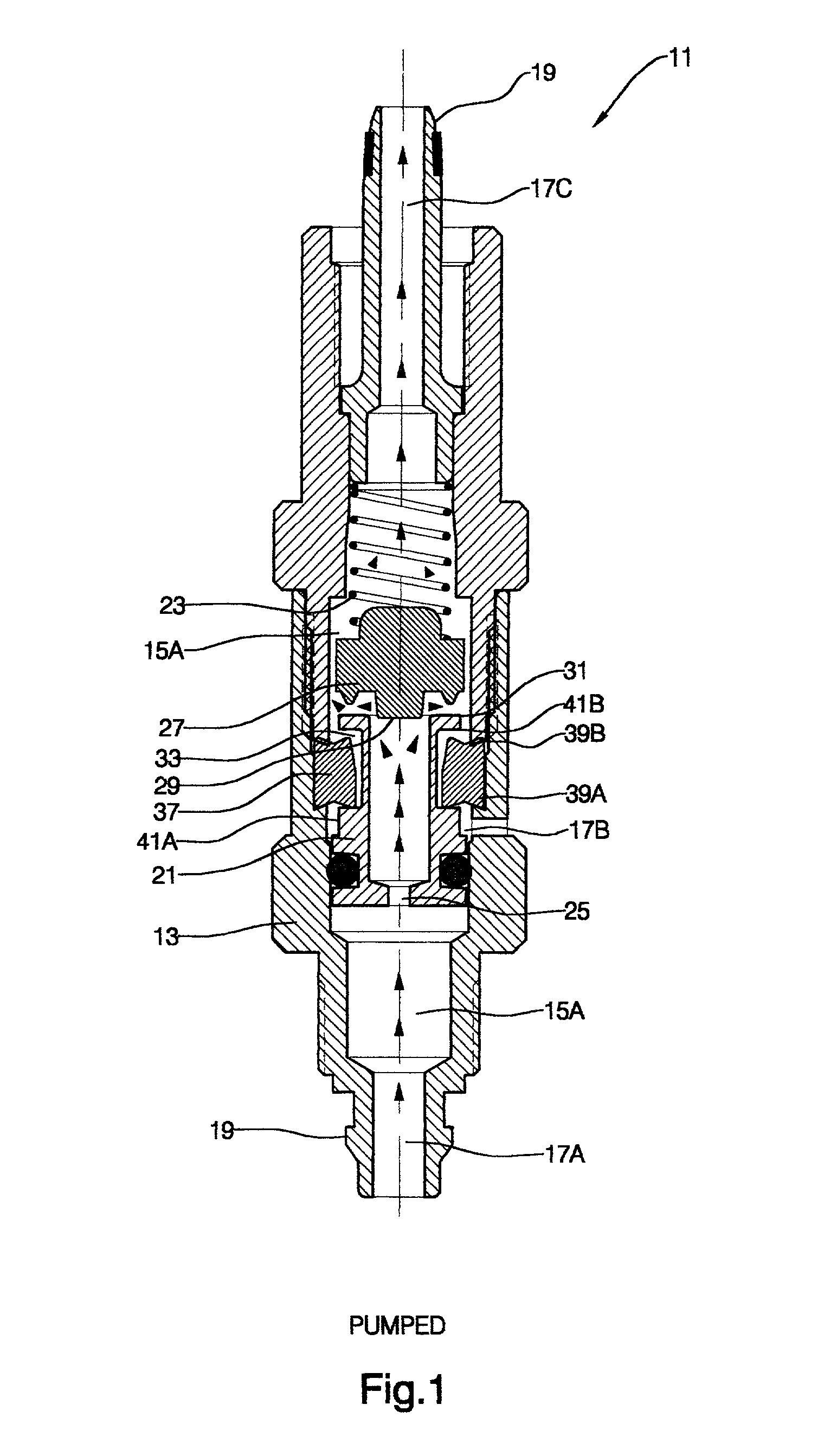
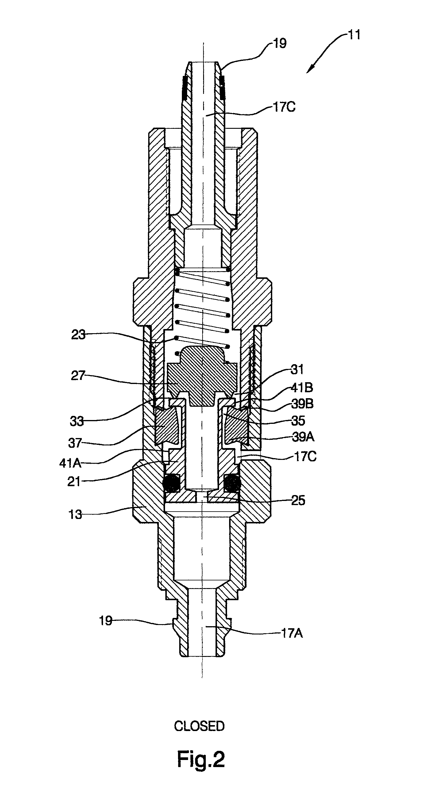
[0026] The embodiments of the valve device according to the invention disclosed in detail hereinafter relate to a valve device for controlling pressure states in a vehicle tire and may be used, for example, as the component designated by reference numeral 39 in the abovementioned Argentine patent application N.sup.o P96.01.04874.

[0027] Construction:

[0028] FIGS. 1, 2 and 3 show a sectional view of a two-valve device 11 according to the present invention. The two-valve device 11 comprises a valve body 13 housing an inlet circuit 15A extending longitudinally between two air ports 17A, 17C provided at respective longitudinally-opposite ends 19 of the valve body 13. The port 17A is for the inflow of inflating air. Accordingly, it is coupled to the pressurizing installation piping (not shown), from which it receives both the inflating airflow and pressure signals for controlling the valve device 11. The port 17C is coupled to the tire tube (not shown), such that it behaves as an inflating...


PUM


Abstract

A remote pressure-controlled three-way valve device has a plunger axially traversed by an inlet passage normally closed by a spring-urged inlet valve. The plunger's outer sidewall has a recess in which an O-ring extends to abut against the steps of the recess to limit the plunger stroke and keep an outlet passage closed to a venting port formed in the sidewall of the body of the device. O-ring prevents short-circuits between the inlet passage and the vent port and a spring for counteracting friction between the O-ring and the device inner wall. Filters arranged in respective ports connectable to the input air-pressure supply and the tire inner tube provide fixed seats for the springs to bear on. The plunger may dwell in a stable intermediate position that opens the outlet or deflation passage is controlled by sending an air pressure through the inlet port at 50% of the normal pressure.

Description

FIELD AND BACKGROUND OF THE INVENTION[0001] The present invention concerns a valve device for installation in pressurized gas or air piping and which may be controlled by means of the relative pressure of the gas applied to one port of the valve device or by the pressure differential between two ports thereof. That is, the state of the valve device may be remote-controlled via the air pressure in the pipe connected to that port, without auxiliary control lines, by varying the air pressure applied to the other end of the piping. In particular, it concerns a three-state valve device adapted to operatively adopt (i) a closed position, (ii) an open position between one pair of ports or (iii) an open position between another pair of ports, according to the pressure state in one of the ports, i.e. the valve control port.[0002] The invention further refers to a method for governing the states of the valve device via the pressurized-gas pressure state in the piping of the installation.[0003...

Claims


Application Information

Patent Timeline
IPC IPC(8): B60C23/00F16K11/10
CPCF16K11/10B60C23/003Y10T137/2544Y10T137/3646B60C23/00363B60C23/00354
Inventor COLUSSI, RAFAEL A.VENICA, NESTOR J.
Owner COL VEN
Learn More