
Fuel injection valve and method for operating the same

a technology of fuel injection valve and fuel injection valve, which is applied in the direction of non-mechanical valves, electrical control, magnetic bodies, etc., can solve the problems of increasing the space required by the circuit, complex design of the corresponding control element, and shortening the closing tim

Inactive Publication Date: 2002-11-21
ROBERT BOSCH GMBH
View PDF7 Cites 7 Cited by
  • Summary
  • Abstract
  • Description
  • Claims
  • Application Information

AI Technical Summary

Benefits of technology

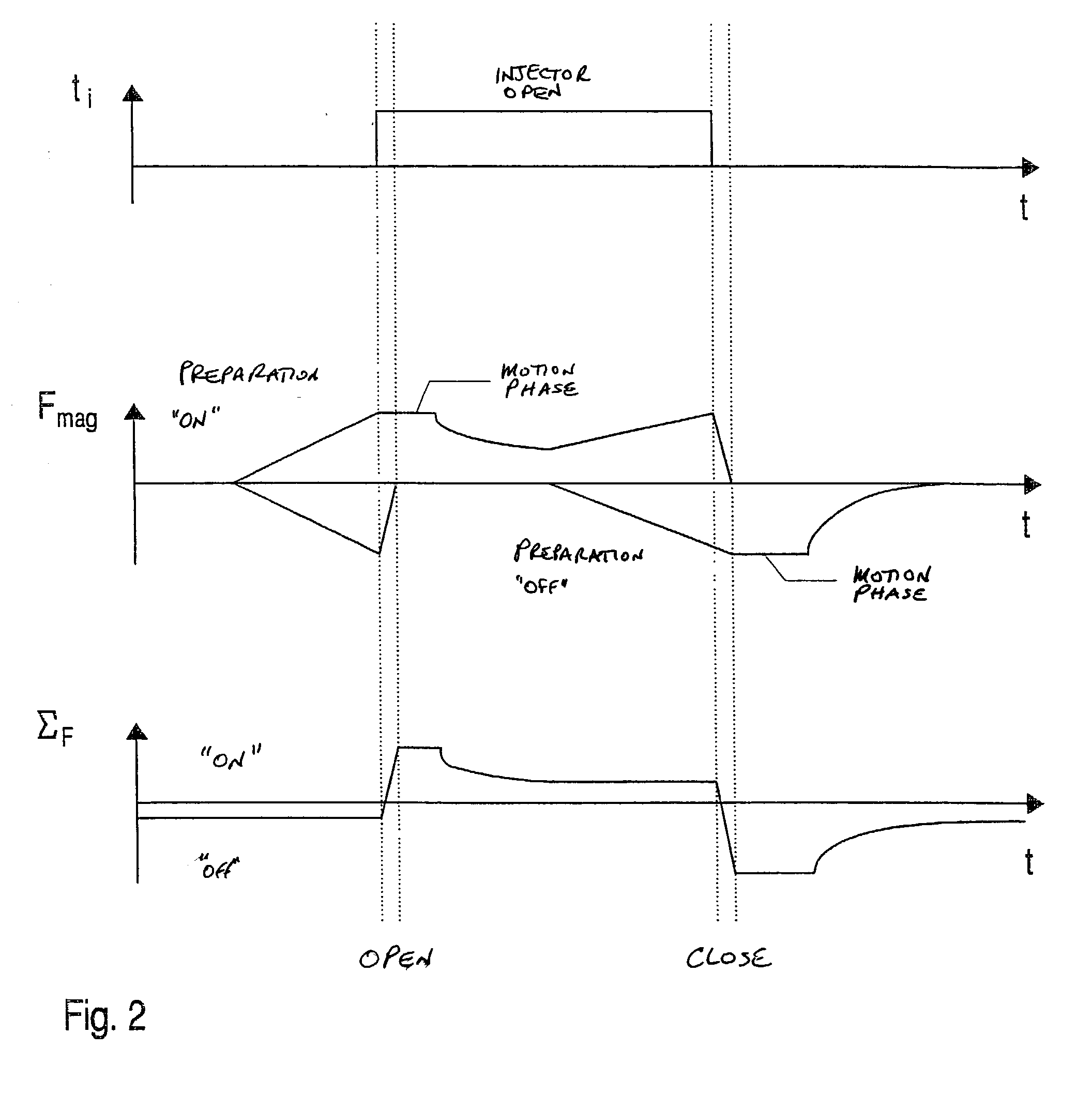
[0006] The fuel injector according to the present invention having the features of claim 1 has the advantage over the related art that a closing force can be generated in the closing direction using the first solenoid. According to the method described in claim 10, the opening operation can be prepared by energizing both solenoids and subsequently switching off the solenoid acting in the closing direction. The beginning of the injection operation is then advantageously triggered by switching off one of the two solenoids, which is the opposite of the mode of operation of the conventional arrangement, where the opening operation is triggered by energizing the solenoid. The switching dynamics are positively influenced by the magnetic fields already present, which results in short opening times. The reverse procedure can be used in the closing operation in order to achieve short closing times.[0007] Advantageous refinements of and improvements on the fuel injector described in claim 1 and the method described in claim 10 are possible through the measures presented in the subclaims.[0008] The influence of eddy currents can be reduced by providing the magnetic circuit, e.g., the core parts or the injector housing, with an axial slit.[0009] A radial gap between the magnetic circuits, which is filled with a non-magnetizable material, results in maximizing the magnetic forces, since the magnetic flux is weakened as it passes through the insulating material. Thus the magnetic fields do not interfere with one another.[0010] The maximum force and a force equilibrium can be adjusted via the length in the radial direction of the gap arranged between the solenoids. The position of the gap in the axial direction with respect to the two solenoids allows the arrangement to be made symmetrical.[0011] Also advantageous is energizing the two solenoids with currents of opposite polarities and approximately the same intensity, which induce two opposite fields.[0012] Also advantageous are recesses in the armature parts, which allow the weight of the movable parts to be substantially reduced without affecting the magnetic force.

Problems solved by technology

The design of the corresponding control element is, however, complex and also only results in a slight shortening of the closing time.
The disadvantage of the fuel injector known from German Patent 23 06 007 C3 is in particular the complex manufacturing process of an arrangement having three circuits, which supply three windings of the solenoid.
The increased space required by the circuits is another disadvantage.

Method used


Image

  • Fuel injection valve and method for operating the same
  • Fuel injection valve and method for operating the same
  • Fuel injection valve and method for operating the same

Examples


Embodiment Construction

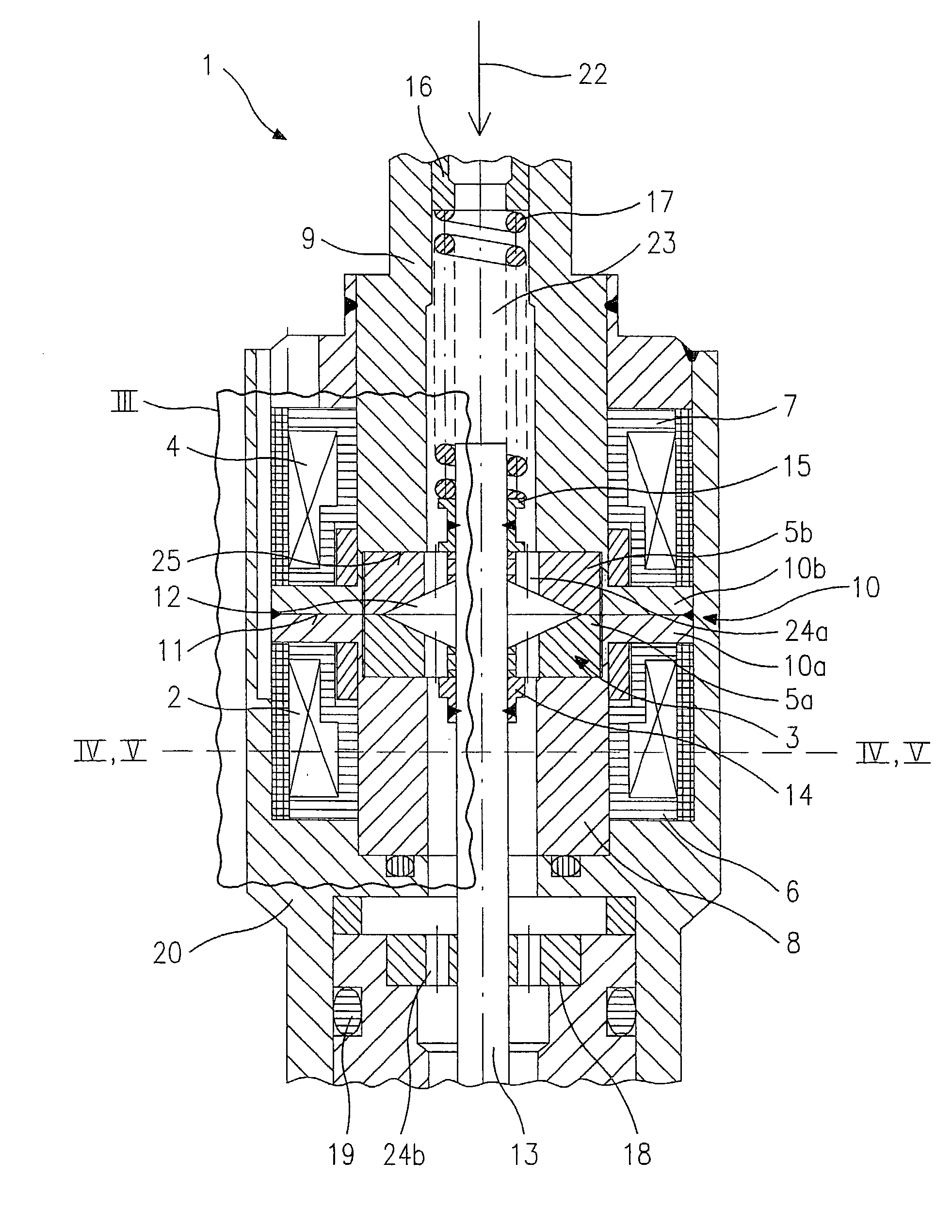
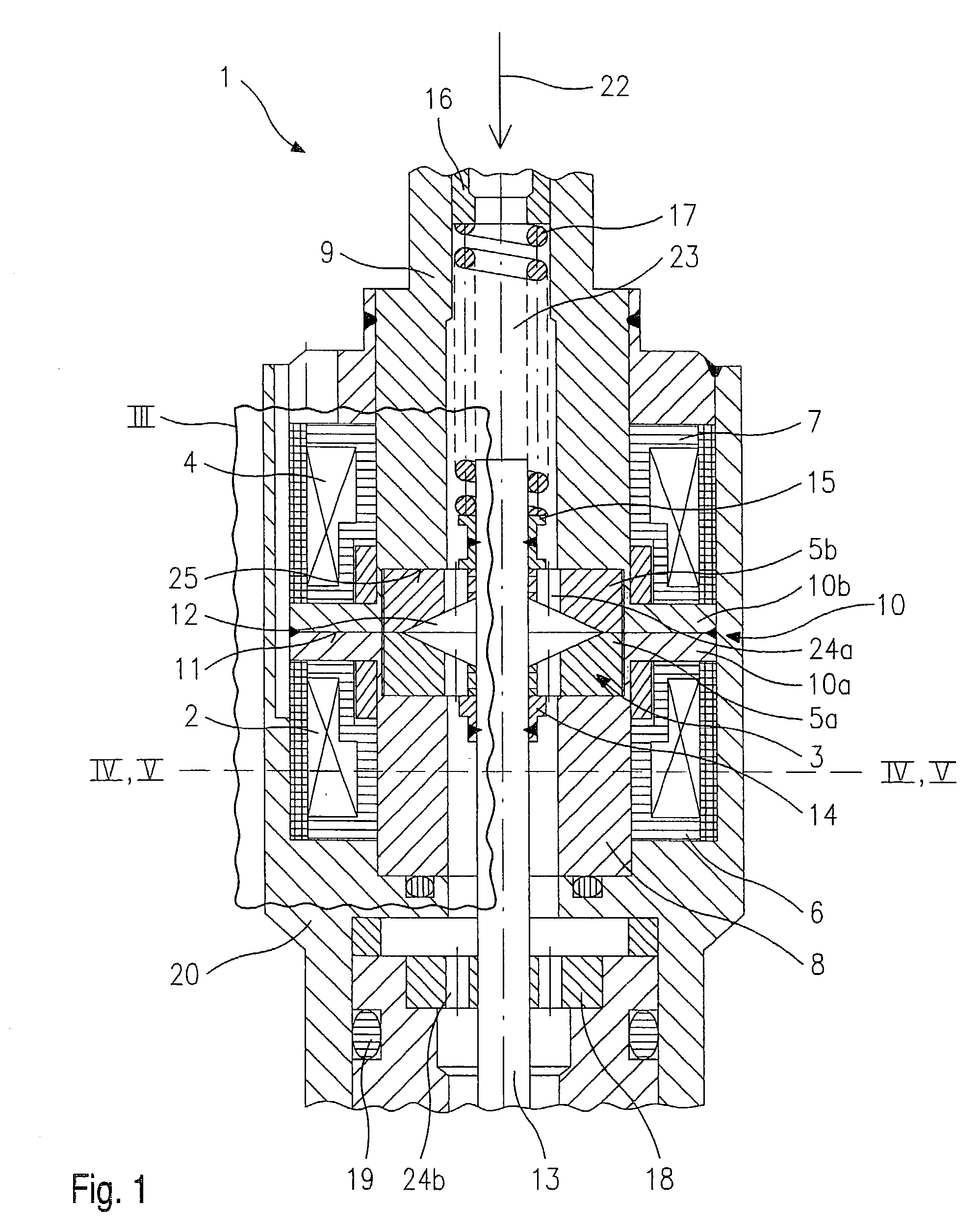
[0019] FIG. 1 shows a partial section through the central part of a fuel injector 1. Fuel injector 1 is designed in particular for direct injection of fuel into a combustion chamber (not illustrated) of an internal combustion engine in which a compressed mixture is externally ignited. Fuel injector 1 can be designed as an inward-opening or an outward-opening fuel injector 1. The embodiment illustrated in FIG. 1 is an inward-opening fuel injector 1.

[0020] Fuel injector 1 includes a first solenoid 2, which cooperates with a first armature part 5a of an armature 3, which is a two-part armature in this embodiment, and a second solenoid 4, which cooperates with a second armature part 5b of armature 3. First solenoid 2 is wound onto a first field spool 6 and second solenoid 4 is wound onto second field spool 7. First solenoid 2 surrounds a first core part 8, while second solenoid 4 surrounds a second core part 9. First solenoid 2 and second solenoid 4 are separated in the axial direction ...


PUM


Abstract

A fuel injector (1), in particular a fuel injector (1) for fuel injection systems, includes a first solenoid (2) cooperating with an armature (3), a second solenoid (4) cooperating with the armature (3), and a valve needle (13) friction-locked to the armature (3) for actuating a valve closing body, a force being exertable on the armature (3) in a closing direction using the first solenoid (2) and in an opening direction using the second solenoid (4).

Description

BACKGROUND INFORMATION[0001] The present invention is based on a fuel injector according to the preamble of claim 1 and a method of operating a fuel injector according to the preamble of claim 10.[0002] The closing times of fuel injectors are lengthened by adhesion forces between armature and core, as well as by eddy currents. It is known that delays can be reduced by making a current flow through the solenoid in the reverse direction at the end of the current pulse which excites the fuel injector in order to accelerate the decay of the residual field. The design of the corresponding control element is, however, complex and also only results in a slight shortening of the closing time.[0003] Another option is to build up one magnetic field to open the fuel injector and a second magnetic field to hold the fuel injector in its open position. The intensity of the holding field can then be selected to be sufficiently low for the eddy currents to be small after the holding field is shut o...

Claims


Application Information

Patent Timeline
IPC IPC(8): F01L9/20F02D41/20F02M51/00F02M51/06
CPCF01L9/04F02D41/20H01F2007/1676F02M51/0617F02M51/0671F02D2041/2079F01L9/20
Inventor RIEGER, FRANZMAISCH, HARALDHUEBEL, MICHAELBECKER, ULRICHSTEIN, JUERGEN
Owner ROBERT BOSCH GMBH
Learn More