Use of standoffs to protect atomic resolution storage mover for out-of-plane motion

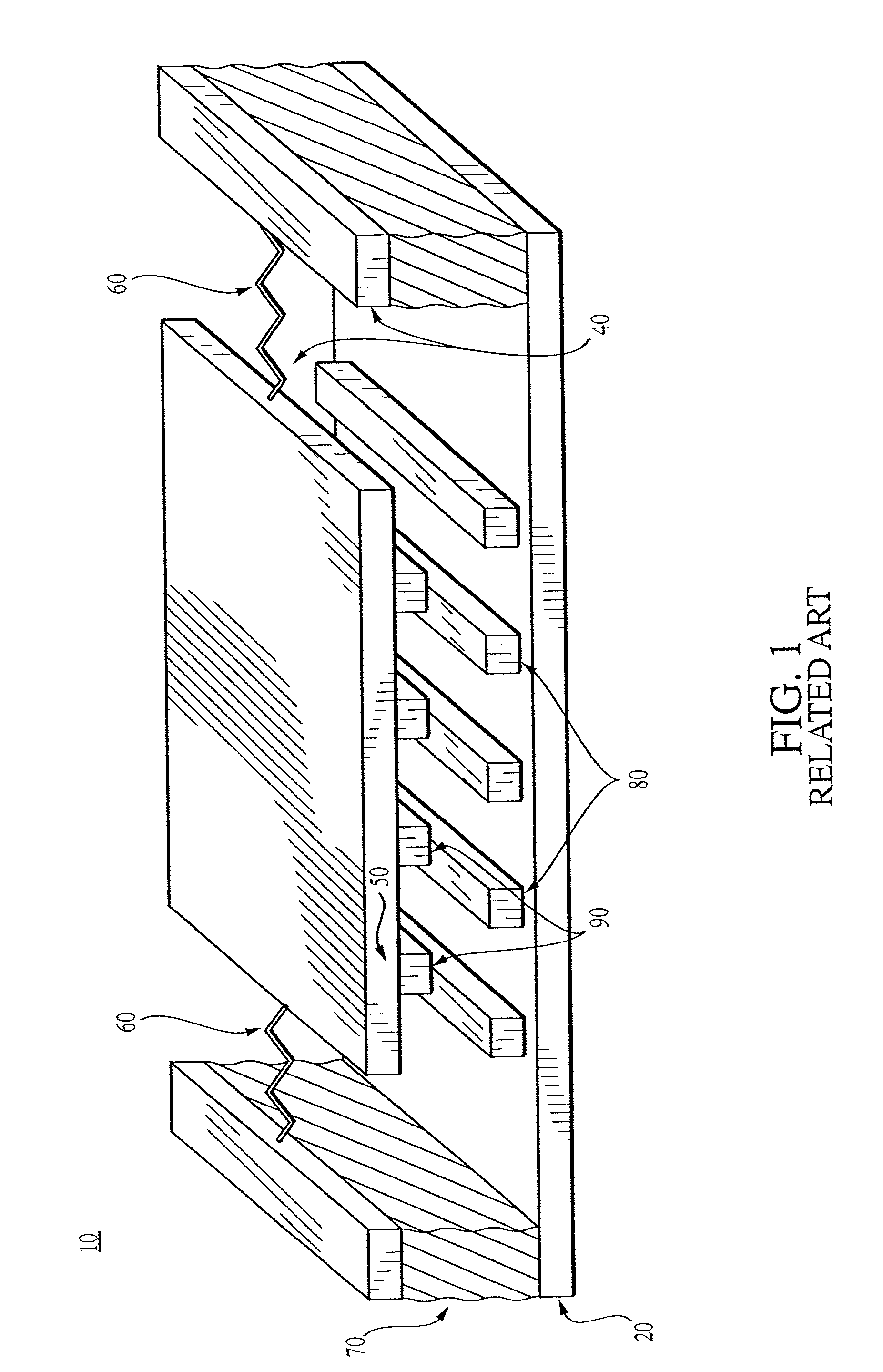
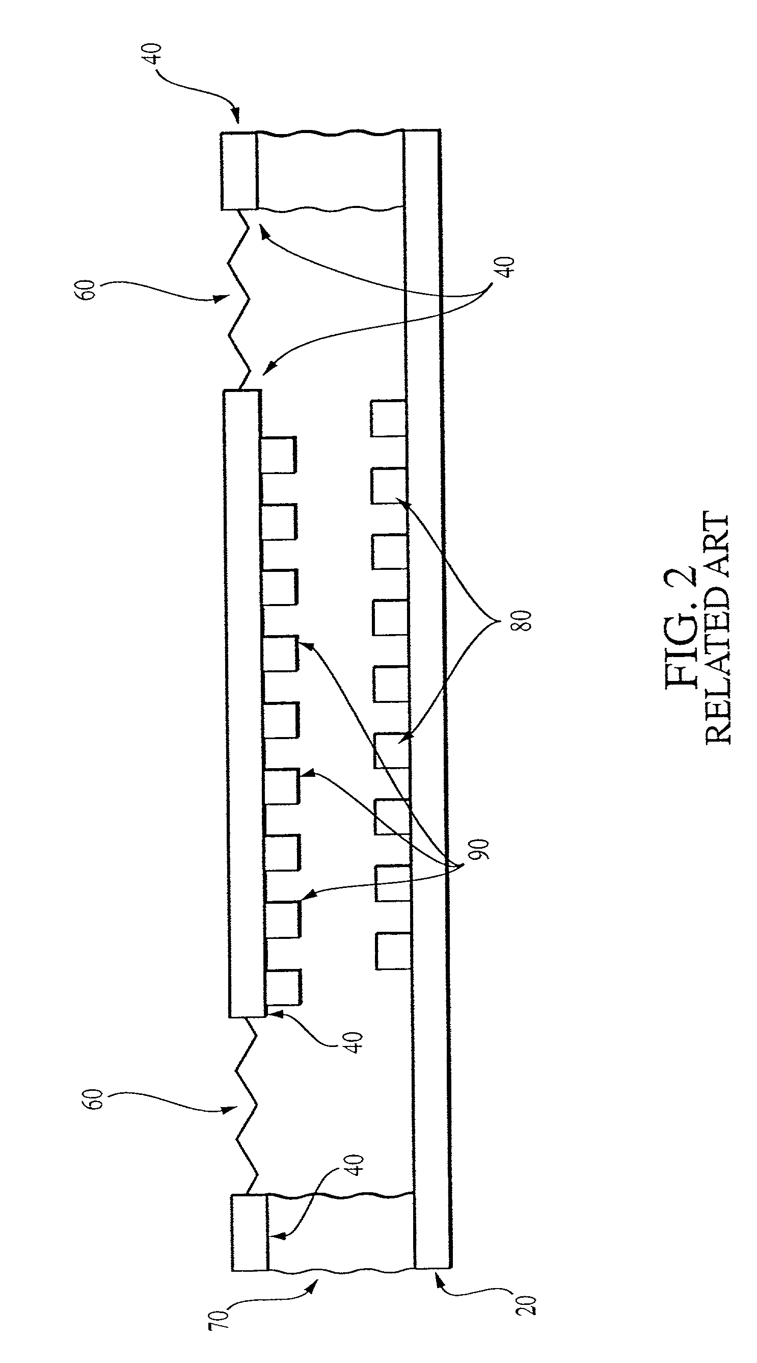
a technology of atomic resolution storage and standoffs, which is applied in the direction of generators/motors, latching devices, and snap-action arrangements, etc., can solve the problems of catastrophic failure of micro-machined actuators 10, and none of these suspensions 60 can prevent out-of-plane motion completely,

Inactive Publication Date: 2002-11-21
HEWLETT PACKARD DEV CO LP
View PDF1 Cites 9 Cited by
  • Summary
  • Abstract
  • Description
  • Claims
  • Application Information

AI Technical Summary

Benefits of technology

[0021] According to one embodiment, an actuator that includes a stator wafer, a first stator electrode protruding from a first surface of the stator wafer, a micro-mover above the first surface of the stator wafer, a first actuator electrode protruding from a first surface of the micro mover, wherein the first surface of the micro-mover and the first surface of the stator face each other, and a first bumper positioned between the stator wafer and the micro-mover.

Problems solved by technology

However, none of these suspensions 60 can prevent out-of-plane motion completely.
Such an event causes catastrophic failure of the actuator 10.
Hence, to date, micro-machined actuators 10 have been susceptible to catastrophic failure.

Method used


Image

  • Use of standoffs to protect atomic resolution storage mover for out-of-plane motion
  • Use of standoffs to protect atomic resolution storage mover for out-of-plane motion
  • Use of standoffs to protect atomic resolution storage mover for out-of-plane motion

Examples


Embodiment Construction

:

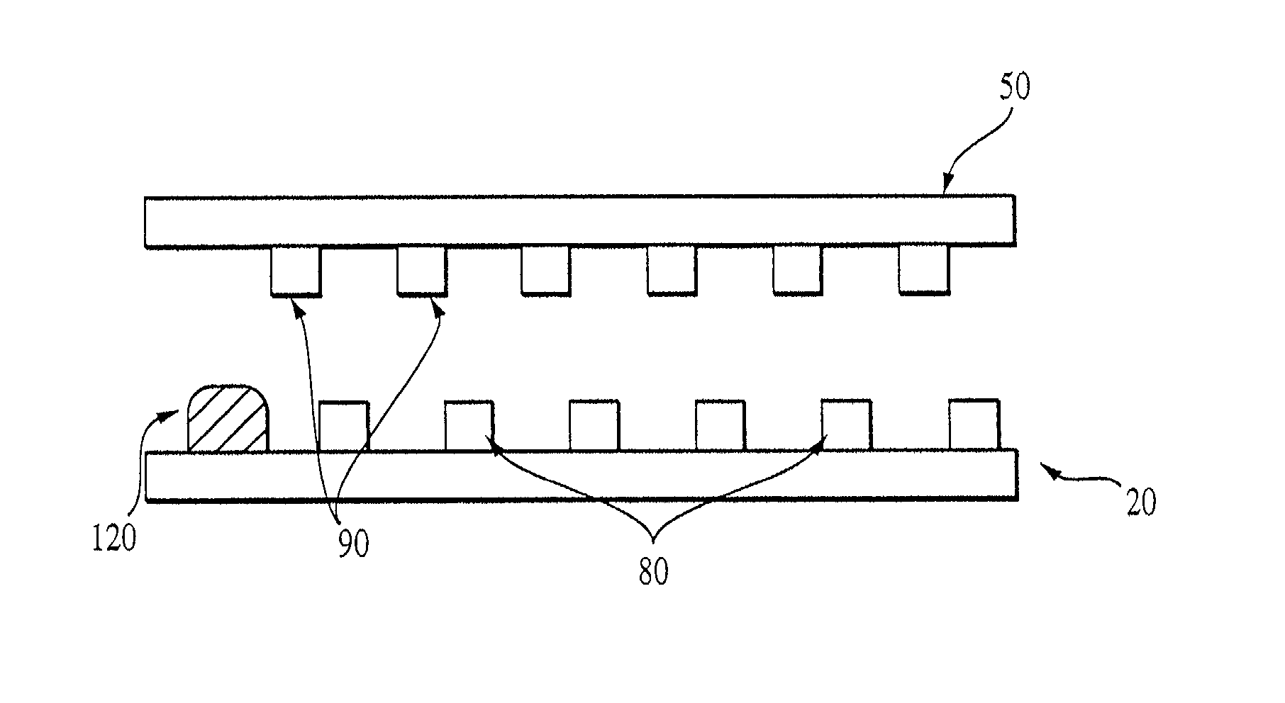
[0033] FIG. 3 illustrates one embodiment of the present invention wherein the stator wafer 20 surface closest to the micro-mover 50 has upon it not only stator electrodes 80 but also a bumper 120. Although the bumper 120 is positioned adjacent to only one stator electrodes 80, this configuration is not restrictive of the present invention. In fact, as shown in FIG. 4, the bumper 120 can easily be position between any two of the stator electrodes 80.

[0034] FIG. 5 illustrates another embodiment of the present invention with two bumpers, a first bumper 120 on the surface of the stator wafer 20 closest to the micro-mover 50, and a second bumper 121 on the surface of the micro-mover 50 closest to the stator wafer 20. Although both bumpers 120,121 illustrated in FIG. 5 are positioned to the outside of the electrodes 80,90, either or both of the bumpers can be positioned between two electrodes 80,90, as shown in FIG. 4.

[0035] FIGS. 6A and 6B illustrate yet other embodiments of the present...


PUM


Abstract

A micro-machined actuator for use in, among other things, sensors and data storage devices. The actuator includes a stator wafer and a micro-mover positioned adjacent to the stator wafer. Between the stator wafer and the micro-mover are electrodes that are set to specified voltages and that emanate electric fields that position the micro-mover relative to the stator wafer. Also between stator wafer and the micro-mover are bumpers that prevent the electrodes from coming into contact with each other.

Description

BACKGROUND OF THE INVENTION:[0001] 1. Field of the Invention[0002] The present invention relates generally to micro-machined actuators. The present invention also generally relates to methods for manufacturing and operating micro-machined actuators.[0003] 2. Description of the Related Art[0004] FIG. 1 illustrates a micro-machined actuator 10 according to the related art. The actuator 10 illustrated includes a stator wafer 20 at the bottom thereof and a rotor wafer 40 above the stator wafer 20. The rotor wafer 40 includes a section, called a micro-mover 50, that is separated from the rest of the rotor wafer 40. The micro-mover 50 is connected to the rest of the rotor wafer 40 via suspensions 60. The wafers 20,40 are bonded together by a bond material 70 that both holds the wafers 20,40 together and separates them a specified distance.[0005] On the surface of the stator wafer 20 closest to the rotor wafer 40 is a series of stator electrodes 80. On the surface of the micro-mover 50 clo...

Claims


Application Information

Patent Timeline
Patent Type & Authority Applications(United States)
IPC IPC(8): H02K33/00B81B5/00H02K41/02H02N1/00H02N13/00
CPCH02N1/006
Inventor HARTWELL, PETER G.
Owner HEWLETT PACKARD DEV CO LP
Why Eureka
Try Eureka