
Laser-diode-excited laser apparatus, fiber laser apparatus, and fiber laser amplifier in which laser medium doped with one of Ho3+, Sm3+, Eu3+, Dy3+, Er3+, and Tb3+ is excited with GaN-based compound laser diode

a laser apparatus and laser diode technology, applied in the field of lasers, can solve the problems of difficult to obtain high output power, large gas laser in gas-laser-excited solid-state laser apparatus, and inconvenient use of 3+-doped solid-state laser crystals for color images,

Inactive Publication Date: 2002-11-21
AGILENT TECH INC +2
View PDF8 Cites 18 Cited by
  • Summary
  • Abstract
  • Description
  • Claims
  • Application Information

AI Technical Summary

Problems solved by technology

Nevertheless, the above gas-laser-excited solid-state laser apparatus using the Pr.sup.3+-doped solid-state laser crystal is not suitable for use in recording a color image in a color image recording apparatus since the gas laser in the gas-laser-excited solid-state laser apparatus are large, heavy, and expensive.
On the other hand, since the efficiency of wavelength conversion in the conventional laser-diode-excited solid-state laser apparatuses in which a wavelength of a solid-state laser beam is reduced by using a nonlinear optical crystal is not sufficiently high, it is difficult to obtain high output power.
Therefore, loss in the resonator is great, and thus achievement of high output power becomes more difficult.
Further, in order to match phases in the wavelength conversion in the above laser-diode-excited solid-state laser apparatuses, highly accurate temperature control is required, and therefore the outputs of the laser-diode-excited solid-state laser apparatuses are not stable.
Therefore, the laser-diode-excited solid-state laser apparatuses become expensive.
However, since the quality of the crystal deteriorates with the increase in the indium content, it is practically impossible to sufficiently increase the indium content, and the upper limit of the lengthened wavelength is about 450 nm.
However, since the quality of the crystal also deteriorates with the increase in the arsenic content, the upper limit of the wavelength realizing high output power is about 450 to 460 nm.
However, the conventional GaN-based compound semiconductor lasers cannot emit laser light with output power of

Method used


Image

  • Laser-diode-excited laser apparatus, fiber laser apparatus, and fiber laser amplifier in which laser medium doped with one of Ho3+, Sm3+, Eu3+, Dy3+, Er3+, and Tb3+ is excited with GaN-based compound laser diode
  • Laser-diode-excited laser apparatus, fiber laser apparatus, and fiber laser amplifier in which laser medium doped with one of Ho3+, Sm3+, Eu3+, Dy3+, Er3+, and Tb3+ is excited with GaN-based compound laser diode
  • Laser-diode-excited laser apparatus, fiber laser apparatus, and fiber laser amplifier in which laser medium doped with one of Ho3+, Sm3+, Eu3+, Dy3+, Er3+, and Tb3+ is excited with GaN-based compound laser diode

Examples


fourth embodiment

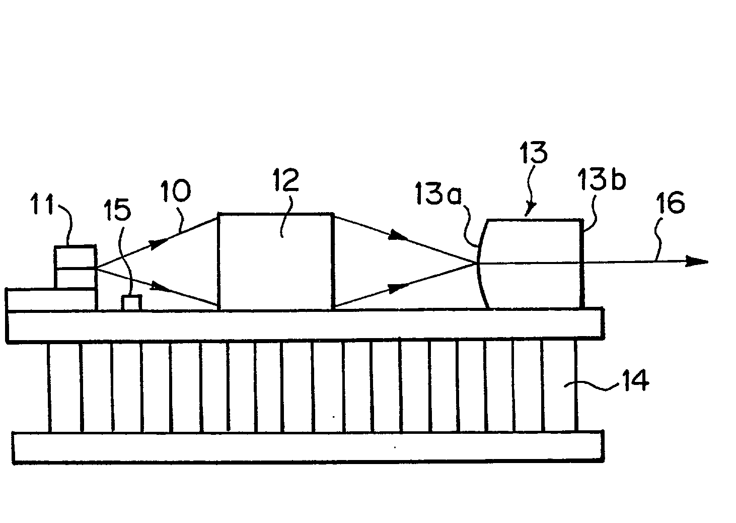
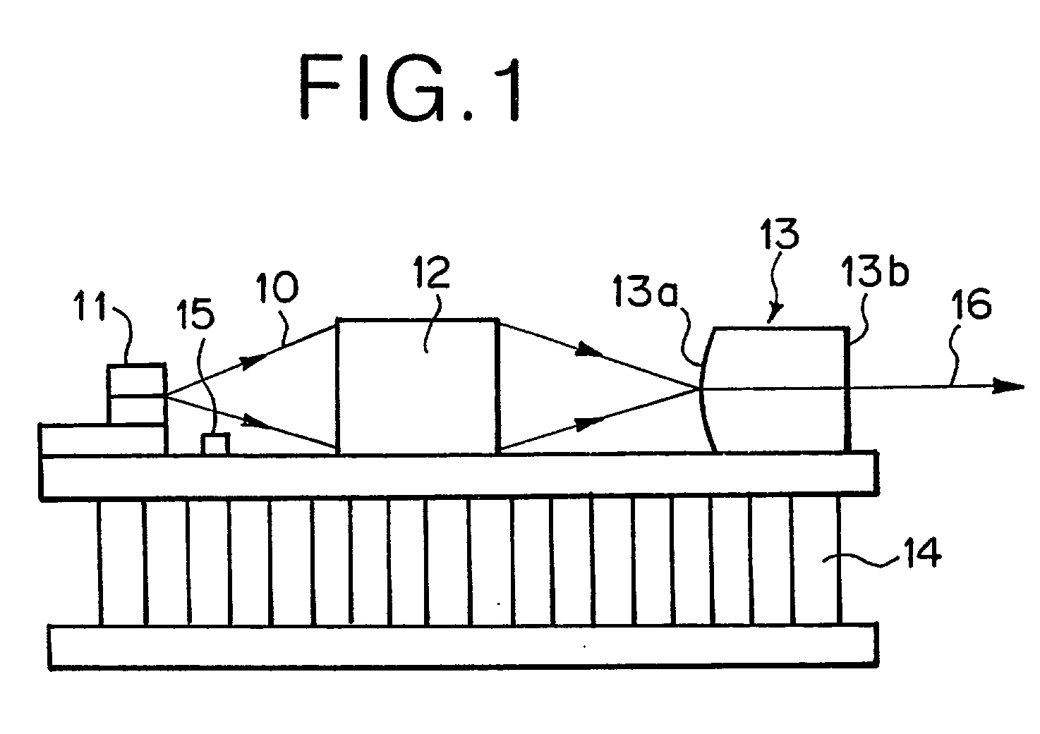
[0227] The fourth embodiment of the present invention is explained below. Since the construction of the laser-diode-excited solid-state laser apparatus as the fourth embodiment of the present invention has the same construction as the first embodiment except for the portions of the construction explained below, the reference numerals in FIG. 1 are also referred to in the following explanations of the fourth embodiment.

[0228] The laser-diode-excited solid-state laser apparatus as the fourth embodiment is different from the laser-diode-excited solid-state laser apparatus as the first embodiment in the rare-earth ion with which the solid-state crystal 13 is doped and the coatings applied to the forward and backward end surfaces 13b and 13a.

[0229] That is, in the fourth embodiment, the solid-state crystal 13 is doped with 1 atomic percent (atm %) of Dy.sup.3+ instead of Ho.sup.3+. In addition, the laser diode 11 used in the fourth embodiment emits a laser beam having the wavelength of 3...

fifth embodiment

[0232] The fifth embodiment of the present invention is explained below. Since the construction of the laser-diode-excited solid-state laser apparatus as the fifth embodiment of the present invention has the same construction as the first embodiment except for the portions of the construction explained below, the reference numerals in FIG. 1 are also referred to in the following explanations of the fifth embodiment.

[0233] The laser-diode-excited solid-state laser apparatus as the fifth embodiment is different from the laser-diode-excited solid-state laser apparatus as the first embodiment in the rare-earth ion with which the solid-state crystal 13 is doped and the coatings applied to the forward and backward end surfaces 13b and 13a.

[0234] That is, in the fifth embodiment, the solid-state crystal 13 is doped with 1 atomic percent (atm %) of Er.sup.3+ instead of Ho.sup.3+. In addition, the laser diode 11 used in the fifth embodiment emits a laser beam having the wavelength of 406 nm....

sixth embodiment

[0238] The sixth embodiment of the present invention is explained below. Since the construction of the laser-diode-excited solid-state laser apparatus as the sixth embodiment of the present invention also has the same construction as the first embodiment except for the portions of the construction explained below, the reference numerals in FIG. 1 are also referred to in the following explanations of the sixth embodiment.

[0239] The laser-diode-excited solid-state laser apparatus as the sixth embodiment is different from the laser-diode-excited solid-state laser apparatus as the first embodiment in the rare-earth ion with which the solid-state crystal 13 is doped and the coatings applied to the forward and backward end surfaces 13b and 13a.

[0240] That is, in the sixth embodiment, the solid-state crystal 13 is doped with 1 atomic percent (atm %) of Tb.sup.3+ instead of Ho.sup.3+. In addition, the laser diode 11 used in the sixth embodiment emits a laser beam having the wavelength of 38...


PUM


Abstract

A solid-state laser crystal constituting a laser-diode-excited solid-state laser apparatus or an optical fiber constituting a fiber laser apparatus or fiber laser amplifier is doped with one of Ho3+, Sm3+, Eu3+, Dy3+, Er3+, and Tb3+ so that a laser beam is emitted from the solid-state laser crystal or the optical fiber, or incident light of the fiber laser amplifier is amplified, by one of the transitions from 5S2 to 5I7, from 5S2 to 5I8, from 4G5/2 to 6H5/2, from 4G5/2 to 6H7/2, from 4F3/2 to 6H11/2, from 5D0 to 7F2, from 4F9/2 to 6H13/2, from 4F9/2 to 6H11/2, from 4S3/2 to 4I15/2, from 2H9/2 to 4I13/2, and from 5D4 to 7F5. The above solid-state laser crystal or optical fiber is excited with a GaN-based compound laser diode.

Description

[0001] The subject matters disclosed in this specification are related to the subject matters disclosed in the following copending, commonly-assigned U.S. patent applications:[0002] (1) U.S. Pat. No. 6,125,132 filed by Yoji Okazaki (one of the applicants of the present patent application) on Apr. 28, 1998 and entitled "LASER DIODE PUMPED SOLID STATE LASER, FIBER LASER AND FIBER AMPLIFIER," corresponding to Japanese patent application Nos. 10(1998)-6369 and 10(1998)-6370, which are laid open in Japanese Unexamined Patent Publication Nos. 11(1999)-17266 and 11(1999)-204862; and[0003] (2) U.S. Ser. No. 09 / 621,241 filed by Yoji Okazaki (one of the applicants of the present patent application) and Takayuki Katoh (another of the applicants of the present patent application) on Jul. 21, 2000 and entitled "LASER-DIODE-PUMPED LASER APPARATUS IN WHICH Pr-DOPED LASER MEDIUM IS PUMPED WITH GaN-BASED COMPOUND LASER DIODE," corresponding to Japanese patent application Nos. 11(1999)-206817 and 11(...

Claims


Application Information

Patent Timeline
IPC IPC(8): H01S3/02H01S3/06H01S3/067H01S3/0941H01S3/109H01S3/16H01S5/323
CPCH01S3/025H01S3/0405H01S3/042H01S3/0602H01S3/067H01S2302/00H01S3/109H01S3/1603H01S3/161H01S3/1615H01S5/32341H01S3/09415
Inventor OHTSUKA, HISASHIOKAZAKI, YOJIKATOH, TAKAYUKI
Owner AGILENT TECH INC
Learn More