Fuel injection device for internal combustion engines

a technology for internal combustion engines and fuel injection devices, which is applied in the direction of fuel injection apparatus, machines/engines, and feed systems, etc., can solve the problems of major leakage flows inadequately uniform opening pressure in the control valve, and the inability to close the nozzle again only with great difficulty

Inactive Publication Date: 2002-12-05
ROBERT BOSCH GMBH
View PDF4 Cites 9 Cited by
  • Summary
  • Abstract
  • Description
  • Claims
  • Application Information

AI Technical Summary

Problems solved by technology

The use of such control valves has the disadvantage, however, that to open and close supply and discharge lines for the fuel that is at high pressure, control edges are provided that typically have small overlaps, which in turn leads to major leakage flows in the control valve.
Hence only an inadequately uniform opening pressure can be established in the control valve.
It is disadvantageous, however, that from the time the nozzle opening pressure is released, the nozzle can be closed again only with great difficulty, since in the opening position of the valve member, the nozzle is constantly subjected to high pressure or to its opening pressure and can accordingly no longer be actively triggered in order to close the control valve and then open it again, for instance for performing a postinjection.

Method used


Image

  • Fuel injection device for internal combustion engines
  • Fuel injection device for internal combustion engines

Examples


Embodiment Construction

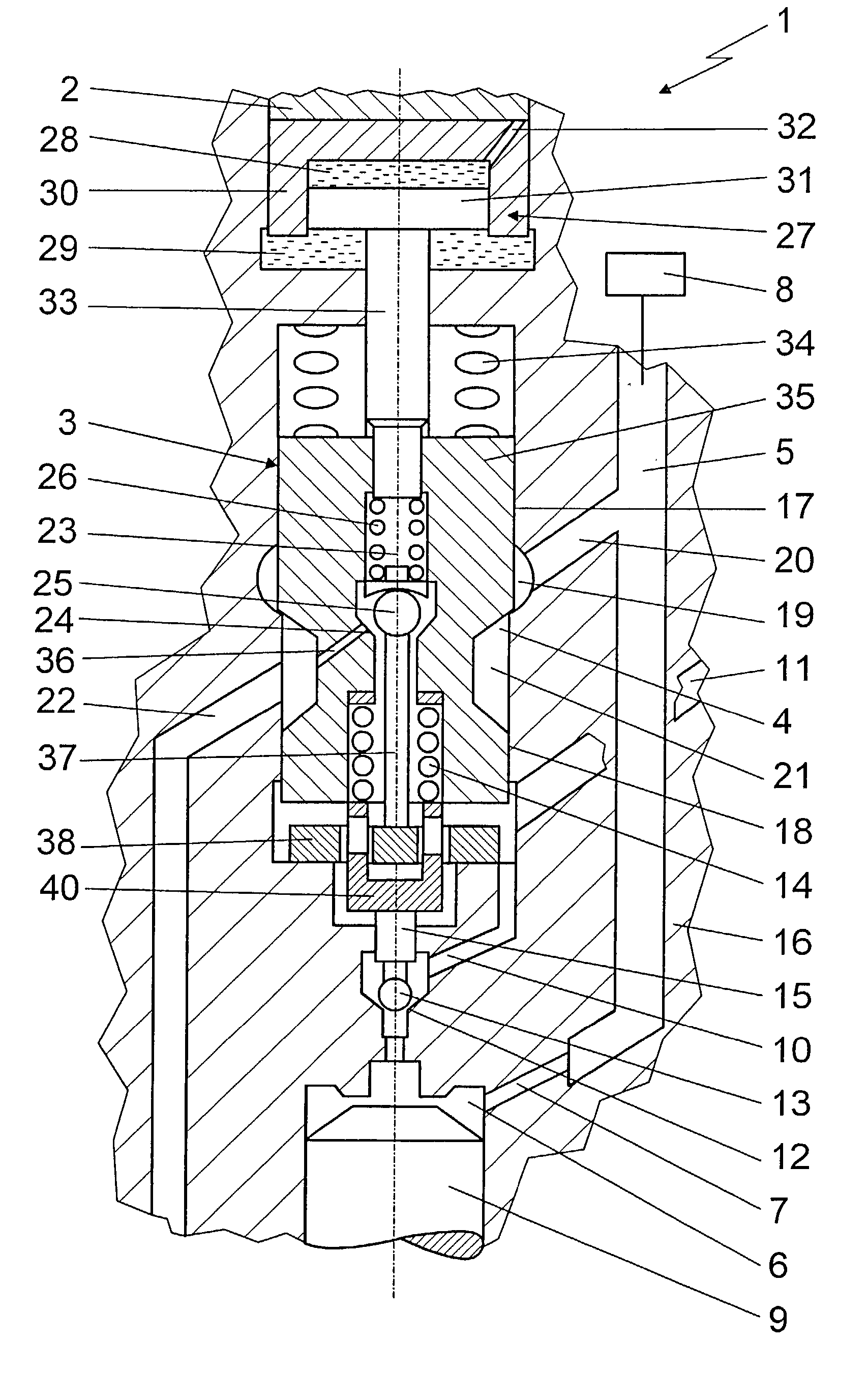
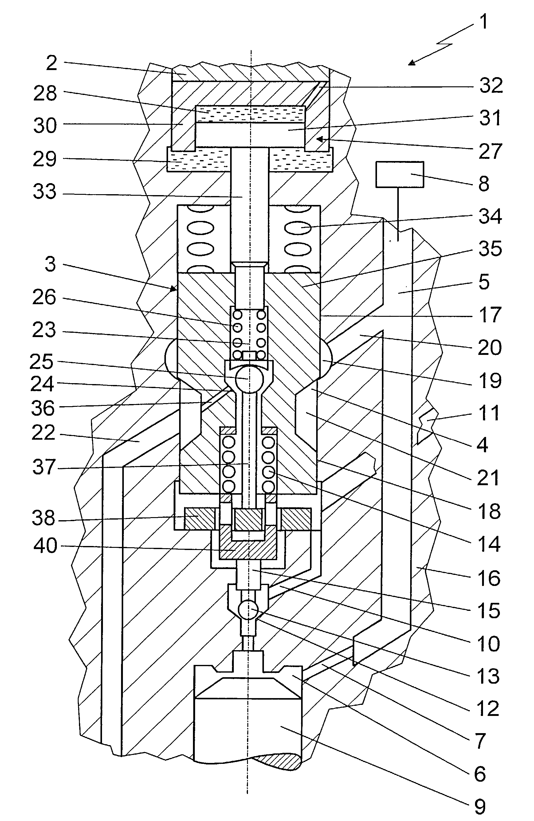
[0014] The exemplary embodiment shown in the drawing shows a fuel injection device 1 in simplified form, with an actuator 2 that is operatively connected to a valve member 3. This valve member 3 is disposed in a high-pressure delivery system of the fuel injection device 1, which connects a high-pressure fuel source 8 to a nozzle chamber, not shown in detail of an injection nozzle, leading into a combustion chamber of an internal combustion engine of the motor vehicle. For displacement of the valve member 3 in a valve housing 16, an actuator 2 is provided, by means of which the valve member 3 is triggerable in such a way that it can be lifted from a first valve seat 4.

[0015] When the valve member 3 is in contact with the first valve seat 4, it disconnects the nozzle chamber from the high-pressure fuel source 8 of the fuel injection device 1. In this position of the valve member 3, no high pressure prevails in the nozzle chamber, and the injection nozzle is closed. A control chamber 6...


PUM


Abstract

A fuel injection device (1) for internal combustion engines, with an injection nozzle that can be supplied with fuel from a high-pressure fuel source (8) and with an actuating element (9) that opens and closes the injection nozzle as a function of the pressure in control chamber (6) is proposed. A high-pressure line (7) discharges into the control chamber (6), and an outflow conduit (10) leads away from the control chamber (6) and can be blocked by a closing element (13) of a valve member (3). A high-pressure delivery system (19, 20, 21, 22) that leads into a nozzle chamber can be blocked by a first valve seat (4) of the valve member (3), and the valve member (3) is movable by a defined stroke length by means of an actuator (2). As a function of this stroke length, the closing element (13) is movable between a closing position and an opening position, the latter relieving the control chamber (6) and allowing an injection (Drawing).

Description

Prior Art[0001] The invention is based on fuel injection devices for internal combustion engines, which are well known in the industry and in which fuel from a high-pressure fuel source is delivered to a nozzle chamber via a control valve in the opening position of a valve member. The fuel delivered to the nozzle chamber at high pressure is injected into a combustion chamber of an internal combustion engine via an injection opening when a nozzle in open. The delivery of fuel to the injection opening is frequently controlled via the control valve, embodied as a slide valve or seat-slide valve, which can be embodied as either force-balanced or partially force-balanced.[0002] The use of such control valves has the disadvantage, however, that to open and close supply and discharge lines for the fuel that is at high pressure, control edges are provided that typically have small overlaps, which in turn leads to major leakage flows in the control valve. Hence only an inadequately uniform o...

Claims


Application Information

Patent Timeline
Patent Type & Authority Applications(United States)
IPC IPC(8): F02M45/00F02M45/02F02M47/02F02M51/00F02M51/06F02M59/46F02M61/10F02M63/00
CPCF02M47/027F02M63/0026F02M63/0007
Inventor BOECKING, FRIEDRICH
Owner ROBERT BOSCH GMBH
Why Eureka
Try Eureka