Rotation detecting device and method of producing same

a technology of detecting device and rotating detector, which is applied in the direction of devices using electric/magnetic means, instruments, coatings, etc., can solve the problems of increasing the cost of the device, failing to provide users with satisfaction, and detecting devices, etc., and achieves the effect of easy production and assembly and the production of the rotation detecting device with eas

Inactive Publication Date: 2002-12-05
UNISIA JECS CORP
View PDF8 Cites 36 Cited by
  • Summary
  • Abstract
  • Description
  • Claims
  • Application Information

AI Technical Summary

Benefits of technology

[0008] It is therefore an object of the present invention to provide a rotation detecting device which is easily produced and assembled.
[0009] It is another object of the present invention to provide a method of producing the rotation detecting device with ease.

Problems solved by technology

However, the rotation detecting devices of the abovementioned publications have failed to provide users with satisfaction.
Specifically, due to inherent constructions, production of the devices needs a complicated assembling process which thus brings about increase in cost of the devices.

Method used


Image

  • Rotation detecting device and method of producing same
  • Rotation detecting device and method of producing same
  • Rotation detecting device and method of producing same

Examples


first embodiment

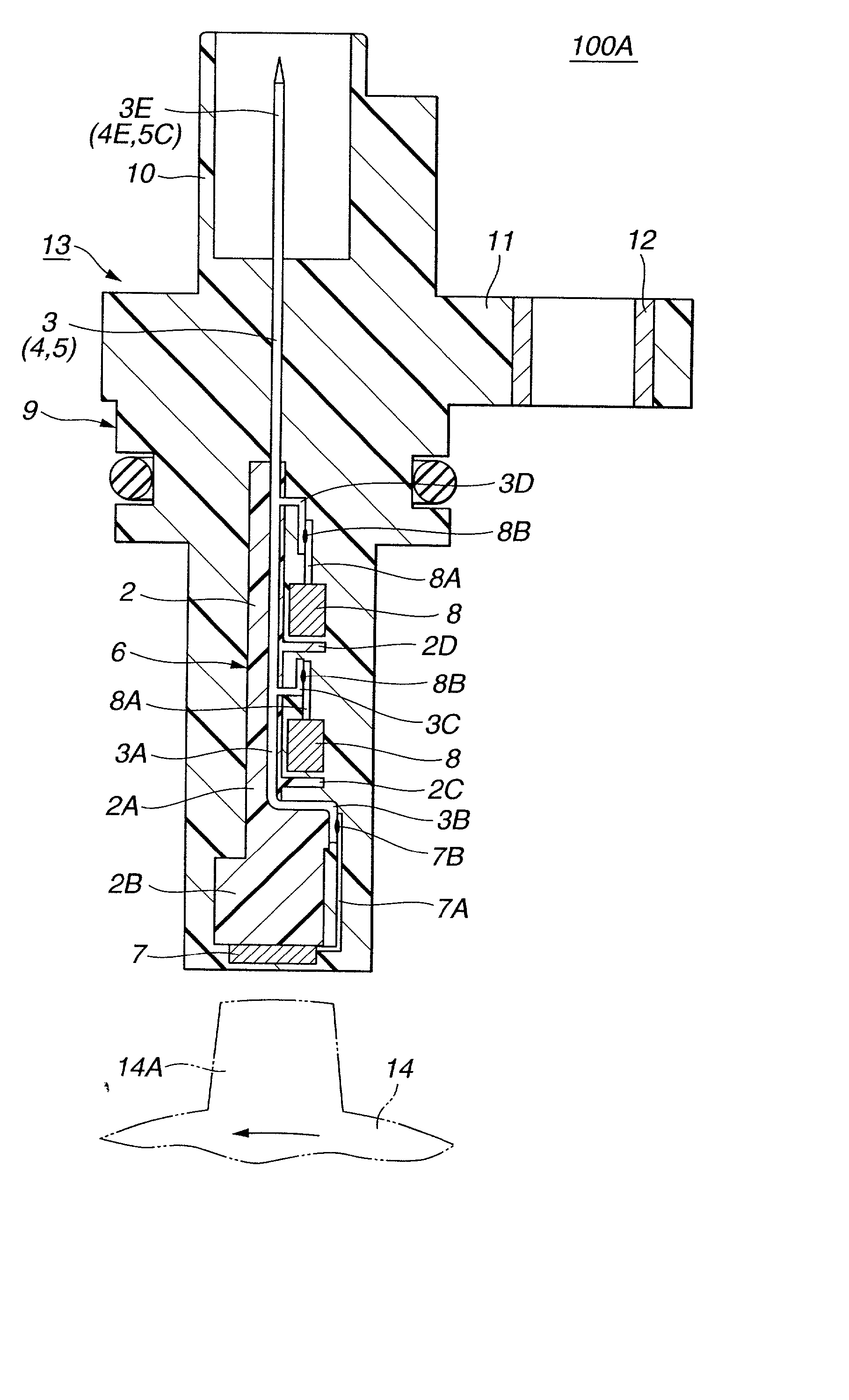
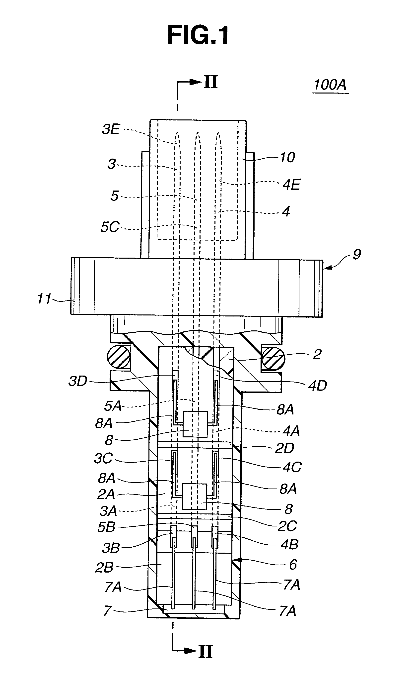
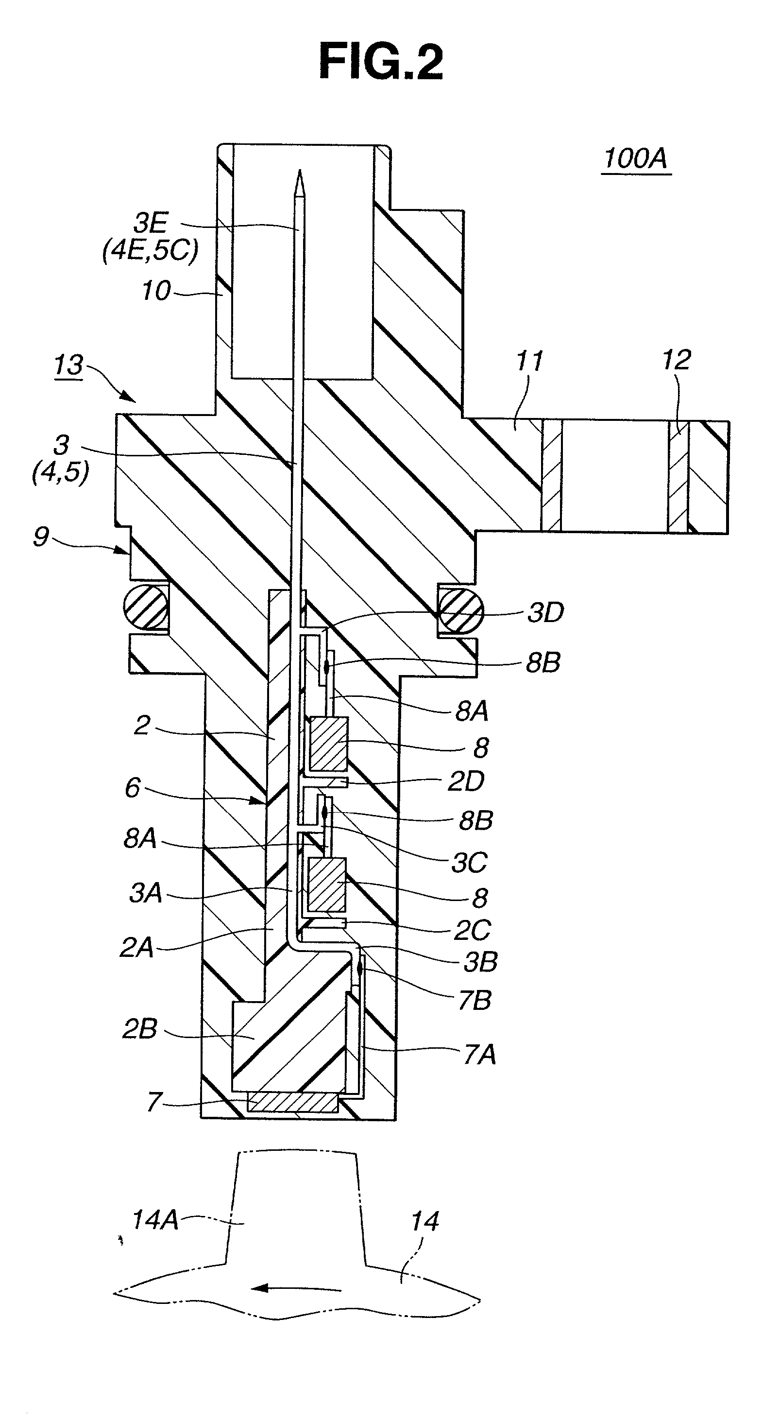
[0030] Referring to FIGS. 1 to 7, particularly FIGS. 1 and 2, there is shown a rotation detecting device 100A of the present invention.

[0031] The rotation detecting device 100A herein shown is a speed detector that detects a rotation speed of an automotive engine.

[0032] In order to facilitate the explanation of the rotation detecting device 100A of the first embodiment, it will be commenced with respect to essential parts of the device 100A.

[0033] In FIG. 5, there is shown a parts-holder 1 that constitutes a base portion of rotation detecting device 100A. As shown, parts-holder 1 comprises generally a molded plastic base 2 and three parallel terminal pins 3, 4 and 5 having lower portions embedded in base 2. As shown, plastic base 2 has a rectangular shape that extends in the same direction as terminal pins 3, 4 and 5. The rectangular plastic base 2 comprises a thinner plate portion 2A, a thicker body portion formed on a lower end of thinner plate portion 2A, and first and second wal...

second embodiment

[0059] Referring to FIGS. 8 to 11, particularly FIG. 8, there is shown a rotation detecting device 100B of the present invention, which is a speed detector for detecting a rotation speed of an automotive engine.

[0060] In the drawings of the second embodiment 100B, parts and elements denoted by the same numerals as those of the abovementioned first embodiment 100A are the same as those in the first embodiment 100A.

[0061] As will become apparent from the following description, in this second embodiment 100B, three, viz., first, second and third molding steps are employed for producing rotation detecting device 100B.

[0062] That is, as is understood when comparing FIG. 8 of the second embodiment 100B with FIG. 2 of the first embodiment 100A, the housing of the device 100B comprises two parts which are produced through respective, viz., second and third molding steps.

[0063] In the following, method of producing rotation detecting device 100B will be described with the aid of the drawings...


PUM

PropertyMeasurementUnit
L-shapeaaaaaaaaaa
rotation speedaaaaaaaaaa
durabilityaaaaaaaaaa

Abstract

A rotation detecting device has the following structure. An intermediate assembly includes terminal pins having projections at given portions thereof; a molded plastic base in which the given portions of the terminal pins are embedded with the projections being exposed to the outside; and a plurality of electronic elements connected to the exposed projections of the given portions of the terminal pins. One of the electronic elements is a sensor element which is mounted on the molded plastic base. A molded plastic housing entirely and hermetically covers the intermediate assembly except a connector part thereof where leading ends of the terminal pins are positioned. For producing the rotation detecting device, two or three molding assemblies are used in order.

Description

BACKGROUND OF INVENTION[0001] 1. Field of Invention[0002] The present invention relates in general to a detector and a method of producing same and more particularly to a rotation detecting device that detects a rotation speed of a rotation member and a method of producing same.[0003] 2. Description of Related Art[0004] Hitherto, as rotation detecting devices, optical and magnetic types have been widely used because these types can detect a rotation speed of a rotation member without contacting the same.[0005] Laid-open Japanese Patent Application (Tokkai) 2000-180460 shows a magnetic type rotation detecting device that detects rotation speed of an automotive road wheel. In the device of this publication, there is used a substrate of insulated plastic material for mounting thereon a given wiring pattern. The plastic material has glass fibers embedded therein for a reliable durability of the substrate. To the substrate, there are further connected through soldering various electronic...

Claims


Application Information

Patent Timeline
Patent Type & Authority Applications(United States)
IPC IPC(8): G01D5/245G01P1/02G01P3/44
CPCY10T29/49146G01P1/026B29C45/14655B29C45/1671
Inventor AOKI, YUHIDEAKIYAMA, SHINJI
Owner UNISIA JECS CORP
Why Eureka
Try Eureka