Lock detection circuit
a detection circuit and lock technology, applied in the direction of oscillator generators, pulse automatic control, electrical devices, etc., can solve the problems of longer time to detect the lock state or the unlock state than is required
- Summary
- Abstract
- Description
- Claims
- Application Information
AI Technical Summary
Benefits of technology
Problems solved by technology
Method used
Image
Examples
Embodiment Construction
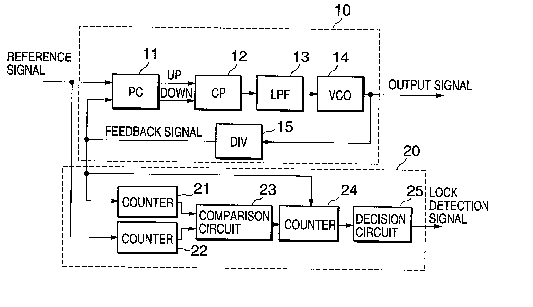
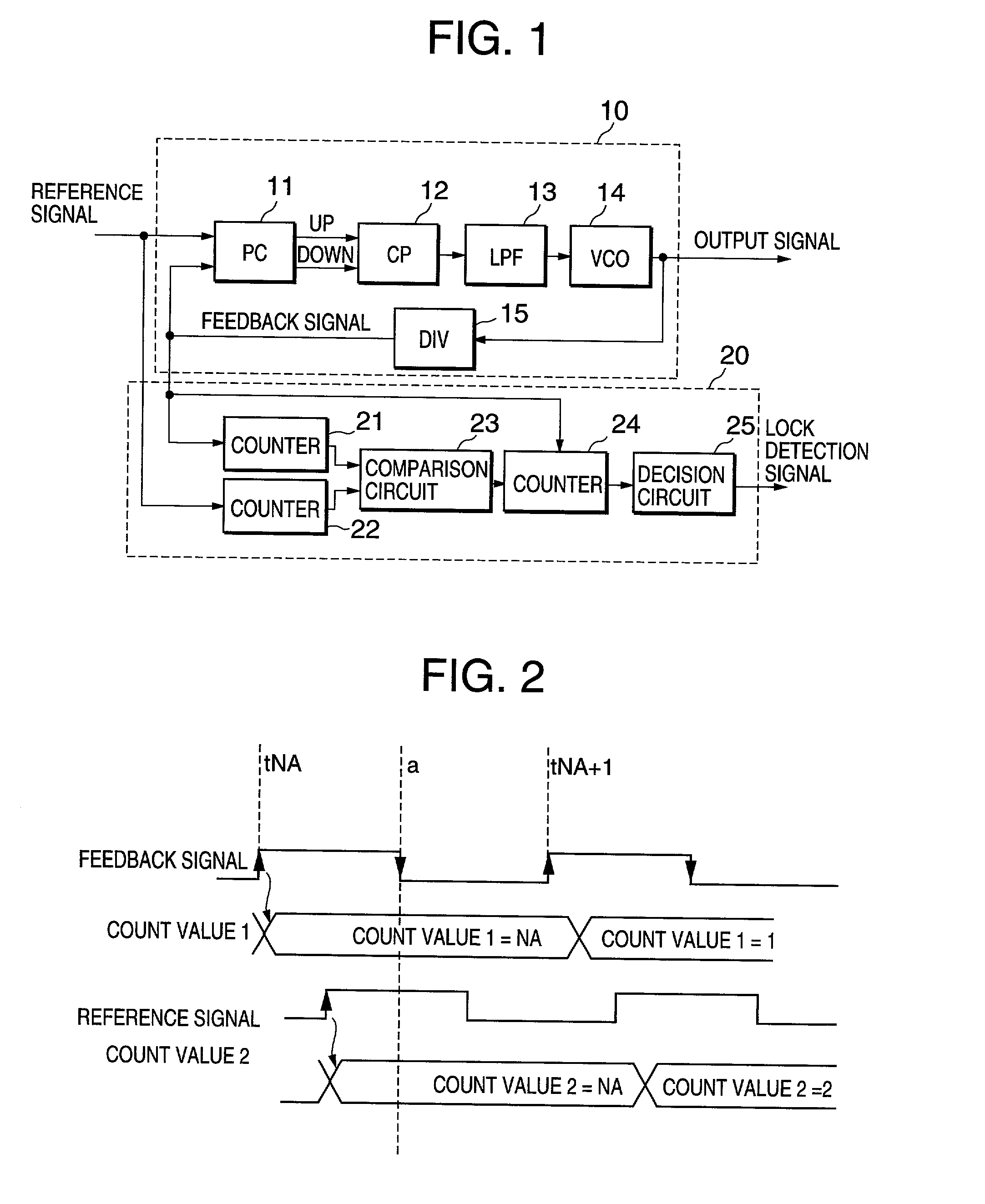
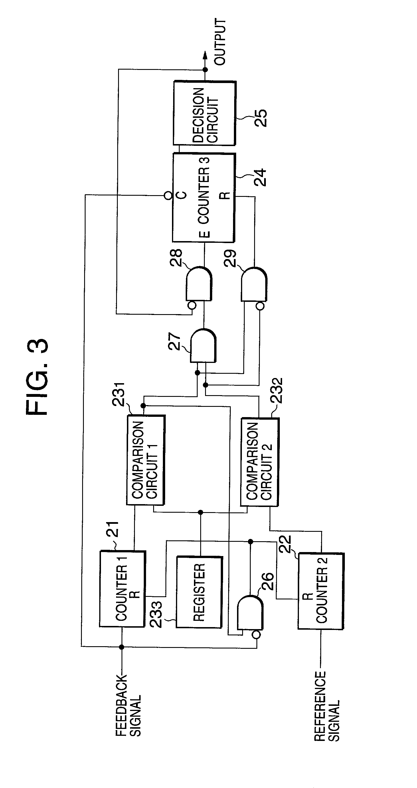
[0032] In order to describe the embodiment of the present invention in greater detail, an embodiment applying the present invention will be described hereinbelow. FIG. 1 is a diagram showing the construction of an embodiment of the present invention. A PLL circuit 10 has a phase comparator (PC) 11; a charge pump 12 for controlling supply of charging and discharging currents to a capacitance, not shown, by an UP signal and a DOWN signal outputted from the phase comparator 11; a loop filter 13 consisting of a low-pass filter to flatten the terminal voltage of the capacitance; a voltage controlled oscillator (VCO) 14 for inputting as a controlled voltage the output voltage of the loop filter 13 to vary an oscillation frequency according to the controlled voltage value; and a frequency divider (DIV) 15 for dividing the output frequency of the voltage controlled oscillator 14. The phase comparator 11 compares the phases between an input reference signal (refereed to as a "reference signa...
PUM
 Abstract
Description
Claims
Application Information
 - R&D
- Intellectual Property
- Life Sciences
- Materials
- Tech Scout
- Unparalleled Data Quality
- Higher Quality Content
- 60% Fewer Hallucinations
Browse by: Latest US Patents, China's latest patents, Technical Efficacy Thesaurus, Application Domain, Technology Topic, Popular Technical Reports.
© 2025 PatSnap. All rights reserved.Legal|Privacy policy|Modern Slavery Act Transparency Statement|Sitemap|About US| Contact US: help@patsnap.com


