Wireless communications architecture

a technology of wireless communication and wired communication, applied in the field of wireless communications, can solve the problems of limited number of available frequency pairs (channels), limited bandwidth that can be installed within a given region, and the demand for forward bandwidth is growing much faster than the demand for reverse bandwidth

a technology of wireless communication and wired communication, applied in the field of wireless communications, can solve the problems of limited number of available frequency pairs (channels), limited bandwidth that can be installed within a given region, and the demand for forward bandwidth is growing much faster than the demand for reverse bandwidth

US20020183063A1Inactive Publication Date: 2002-12-05ARRIS SOLUTIONS

Image

  • Wireless communications architecture
  • Wireless communications architecture

Examples


example

[0022] A specific embodiment of the invention will now be further described by the following, nonlimiting example which will serve to illustrate in some detail various features of significance. The example is intended merely to facilitate an understanding of ways in which the invention may be practiced and to further enable those of skill in the art to practice the invention. Accordingly, the example should not be construed as limiting the scope of the invention.

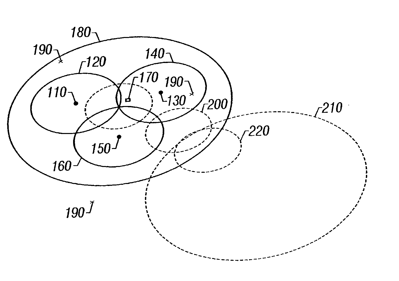
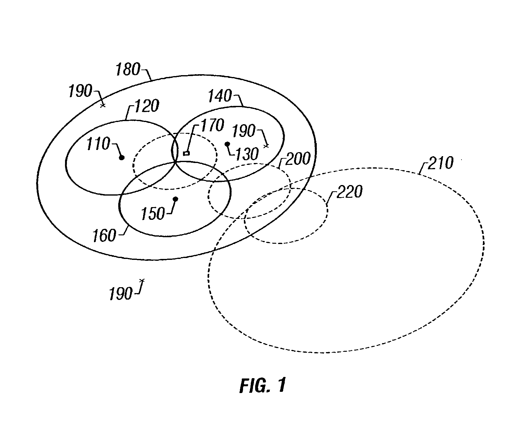
[0023] Referring to FIG. 1, a wireless communications system is depicted. The system includes a plurality of downstream transmitters. A first downstream transmitter 110 covers a first downstream area 120. A second downstream transmitter 130 covers a second downstream area 140 that partially overlaps the first downstream area 120. A third downstream transmitter 150 covers a third downstream area 160 that partially overlaps the first downstream area 120 and / or the second downstream area 140. An upstream receiver 170 covers an ...


PUM


Abstract

Systems and methods are described for wireless communications. A method includes providing a wireless communications system having narrow cast bi-directional internet channel capability and defining a substantially nonconflicting regional overlay; then transmitting a downstream signal from a downstream transmitter to a bi-directional transceiver; and transmitting an upstream signal from the bi-directional transceiver to an upstream receiver through the substantially nonconflicting regional overlay. The systems and methods provide advantages because additional capacity can be provided within a saturated region without incurring interference and additional capacity can be provided only in the direction in which it is needed.

Description

[0001] 1. Field of the Invention[0002] The invention relates generally to the field of wireless communications. More particularly, the invention relates to a wireless communications architecture that provides narrow cast bidirectional channels.[0003] 2. Discussion of the Related Art Prior art wireless communications systems, for instance cellular telephone systems, are known to those skilled in the art. For example, a conventional cellular telephone system typically uses a low power UHF geographically distributed architecture of overlapping cells.[0004] A problem with this technology has been that some geographic regions (e.g., cities) have a high demand for service, but there is limit to the amount of bandwidth that can be installed within a given region. The maximum installable bandwidth is limited by at least two constraints. First, there are a limited number of available frequency pairs (channels) due to government regulations. Second, cells with the same, or similar, frequency ...

Claims


Application Information

Patent Timeline
05 Dec 2002
Publication
US20020183063A1
IPC
H04B7/155; H04L12/28; H04W16/00
CPC
H04W16/00
Inventors
SUCHARCZUK, GUY; WOLODKOWICZ, WANDA