Method of manufacturing a rigid internal gear of a wave gear device

a technology of wave gear and internal gear, which is applied in the direction of gear teeth, manufacturing tools, gearing, etc., can solve the problems of loss of the advantages of a wave gear device being lightweight, device becoming considerably heavy, and rigid internal gear accounting for a large proportion of the weight of the components of the wave gear devi

Inactive Publication Date: 2002-12-12
HARMONIC DRIVE SYST IND CO LTD
View PDF17 Cites 43 Cited by
  • Summary
  • Abstract
  • Description
  • Claims
  • Application Information

AI Technical Summary

Problems solved by technology

As a result, the rigid internal gear accounts for a large proportion of the weight of the components of the wave gear device.
In particular, in cases where an attachment flange for attaching a motor or an output-side member is integrally formed or a housing is integrally formed, the device becomes considerably heavy, so that the advantages of a w...

Method used


Image

  • Method of manufacturing a rigid internal gear of a wave gear device
  • Method of manufacturing a rigid internal gear of a wave gear device
  • Method of manufacturing a rigid internal gear of a wave gear device

Examples


second embodiment

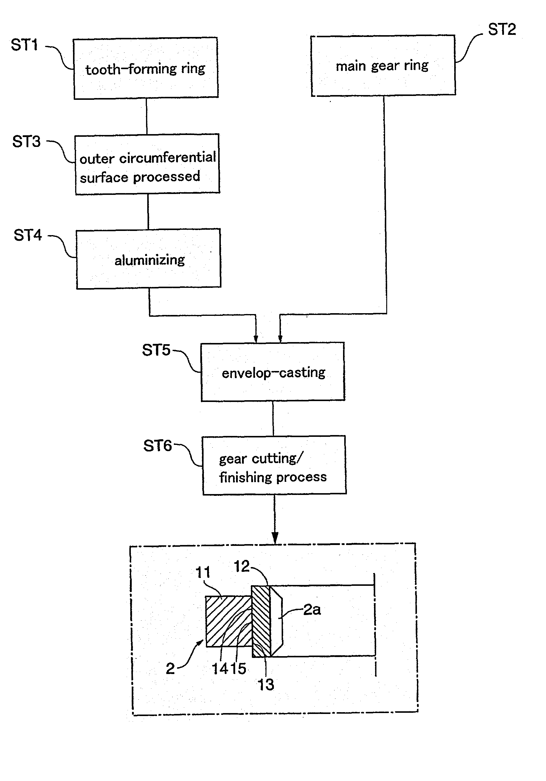
[0043] The following describes a different method for attaching the tooth-forming ring 12 and the main gear ring 11.

[0044] FIG. 4 is a general flowchart showing the manufacturing process of a composite rigid internal gear 2A of the present embodiment. As shown in the drawing, a tooth-forming ring 12 in which the internal teeth 2a have not been formed and a main gear ring 11 are separately manufactured (steps ST11, ST12). In the present embodiment, the tooth-forming ring 12 is formed of an abrasion-resistant and strong material, while the main gear ring 11 is formed of a lightweight material. Also, the materials are chosen so that the linear expansion coefficient of the tooth-forming ring 12 is larger than that of the main gear ring 11. Example combinations of the material and linear expansion coefficient of the tooth-forming ring 12 and those of the main gear ring 11 are shown below.

1 Main gear ring 11 (linear Tooth-forming ring 12 (linear expansion coefficient) expansion coefficien...

third embodiment

[0053] The following describes a different method for attaching the tooth-forming ring and the main gear ring, with reference to FIGS. 6 and 7.

[0054] FIG. 6 is an explanatory view of part of an outer circumferential surface of the tooth-forming ring 12C used in the bonding method of the present embodiment, and FIG. 7 is a general flowchart showing the manufacturing process of a composite rigid internal gear 2C of the present embodiment. The following describes the manufacturing process of the combined rigid internal gear 2C of the present embodiment, with reference to these drawings.

[0055] First, a tooth-forming ring 12C in which the internal teeth 2a have not been formed is manufactured from a ferrous material that is strong and abrasion-resistant (step ST21 in FIG. 7). Also, the main gear ring 11 is manufactured from a lightweight aluminum alloy (step ST22 in FIG. 7).

[0056] Next, a knurling process is performed on the outer circumferential surface 14C of the tooth-forming ring 12C...


PUM

PropertyMeasurementUnit
Thicknessaaaaaaaaaa
Thicknessaaaaaaaaaa
Angleaaaaaaaaaa

Abstract

A rigid internal gear 2 of the wave gear device is composed by integrating a tooth-forming ring 12 formed with internal teeth, and a main gear ring 11 into a single body. The tooth-forming ring 12 is manufactured from a ferrous or copper material that has superior strength and abrasion resistance, while the main gear ring 11 is manufactured from a lightweight material, such as an aluminum alloy. The outer circumferential surface of the tooth-forming ring 12 is aluminized to form a dispersed aluminum coating 15, before the tooth-forming ring 12 is cast within the main gear ring 11 so as to integrate the main gear ring 11 and the tooth-forming ring 12. Both parts are reliably integrated so that a large amount of torque can be transmitted, whereby realizing a rigid internal gear that is lighter than conventional models.

Description

[0001] 1. Field of the Invention[0002] The present invention relates to a method of manufacturing a rigid internal gear of a wave gear device and to a rigid internal gear manufactured by this method of manufacturing. In more detail, the present invention pertains to a method of manufacturing a rigid internal gear that is made lighter with no loss in strength, abrasion resistance, etc., and to such a rigid internal gear.[0003] 2. Related Art[0004] A typical wave gear device includes a circular rigid internal gear, a cup-shaped flexible external gear disposed inside the rigid internal gear, and a wave generator fitted into the flexible external gear. The wave generator normally has an elliptical outline, and the flexible external gear is flexed elliptically so that the flexible external teeth on its outer circumferential surface are partially meshed with the internal teeth of the rigid internal gear. When the wave generator is rotated by a motor or the like, the engaging portions of b...

Claims


Application Information

Patent Timeline
IPC IPC(8): B23K20/00B23F15/00B23P15/14F16H1/32
CPCB23P15/14F16H49/001F16H2055/176Y10T29/4948Y10T74/19Y10T29/49467Y10T29/49464
Inventor KOBAYASHI, MASARUTANIOKA, YOSHIHIRO
Owner HARMONIC DRIVE SYST IND CO LTD
Why Eureka
Try Eureka