
Auger for magnetic materials with specific use for developer transport in electrographic printing systems

a technology of electrographic printing system and auger, which is applied in the direction of electrographic process apparatus, instruments, optics, etc., can solve the problems of toner spilling into other areas of the developer, space or geometry problem, and material packing, and achieve the effect of enhancing the auger screw pitch separation

Inactive Publication Date: 2002-12-12
XEROX CORP
View PDF0 Cites 8 Cited by
  • Summary
  • Abstract
  • Description
  • Claims
  • Application Information

AI Technical Summary

Benefits of technology

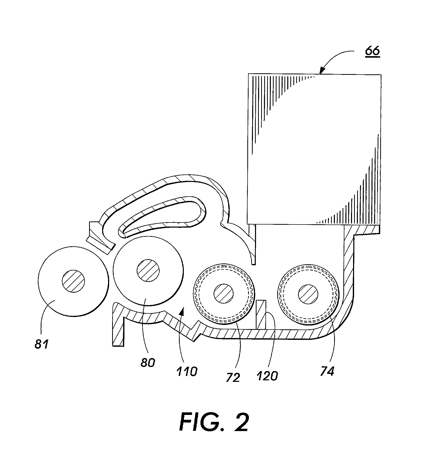
[0009] Applicant has also found that the physical separation of the Is toner into sections by fins in a physical auger can produce differential loading of the mag brush in an auger fed developer system and that the magnetic fields generated by the mag brush donor roll strongly affects the toner in the augers and appears to influence loading of the donor roll in a way to enhance the auger screw pitch separation. This has contributed to diagonal bands (auger mark print defects) being developed onto prints.

Problems solved by technology

A problem with this inter-auger transfer is that the developer is exchanged by a sideways pushing application which requires that the augers be physically close to each other.
For some systems, this proximity requirement may present a space or geometry problem.
A second difficulty with this "push" inter-auger transfer is the tendency for the developer to "bunch up" at the transfer end, sometimes resulting in toner spilling over into other areas of the developer housing unless specific seals are placed at strategic locations.
A third difficulty is that systems having physical augers forces the material in the area of the sump where the auger is closest to the housing, causing packing of the material and in some instances failure of the auger or material property changes as the material binds together under pressure.
Yet another difficulty is that the friction caused by systems which physically push powdered materials by contact augers causes heating and spatial non-uniformities, such as tunnels and tenting, in the materials being transported.
This often can result in poor mixing, poor loading, and even toner block (fusing of the toner material in the housing instead of when heated on the print).
This has contributed to diagonal bands (auger mark print defects) being developed onto prints.

Method used


Image

  • Auger for magnetic materials with specific use for developer transport in electrographic printing systems
  • Auger for magnetic materials with specific use for developer transport in electrographic printing systems
  • Auger for magnetic materials with specific use for developer transport in electrographic printing systems

Examples


Embodiment Construction

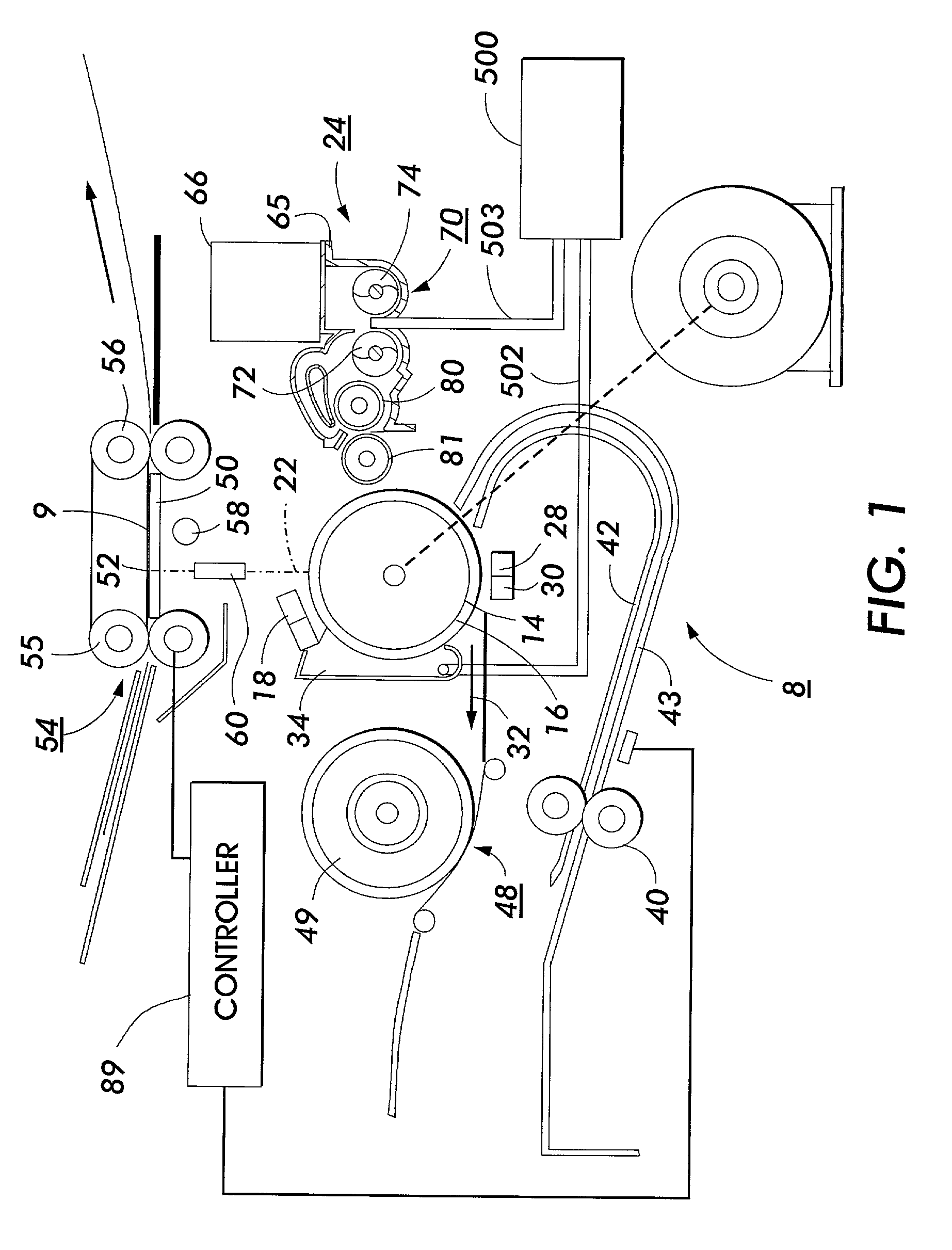
[0015] Referring to FIG. 1 of the drawings, there is shown a xerographic type reproduction machine 8 incorporating the dual auger mixing assembly of the present invention, designated generally by the numeral 10. Machine 8 has a suitable frame (not shown) on which the machine xerographic components are operatively supported.

[0016] Briefly, and as will be familiar to those skilled in the art, the machine xerographic components include a recording member, shown here in the form of a rotatable photoreceptor 14. In the exemplary arrangement shown, photoreceptor 14 comprises a drum having a photoconductive surface 16. Operatively disposed about the periphery of photoreceptor 14 are a charge corotron 18 for placing a uniform charge on the photoconductive surface 16 of photoreceptor 14; an exposure station 22 where the previously charged photoconductive surface 16 is exposed to image rays of a document 9 being copied or printed; development station 24 where the latent electrostatic image cr...


PUM


Abstract

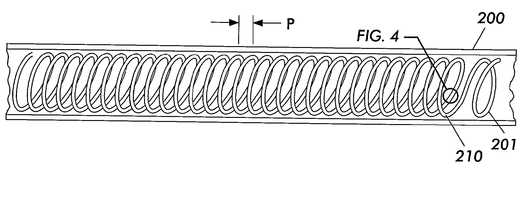
A development system including a housing, a developer roll mounted in the housing, for depositing marking particles on an imaging surface having an electrostatic latent image thereon, an auger, for mixing and transporting the marking particles and carrier constituents of the developing material and; transferring mixed developer material to the developer roll, the auger comprising an elongate strip of magnetic material having a helix structure; a nonmagnetic sleeve enclosing the elongate strip of magnetic material; and means for rotating the elongate strip of magnetic material within the nonmagnetic sleeve, the elongate strip of magnetic material generates a magnetic field for transporting the developer material axially along an outer surface of the nonmagnetic sleeve when rotated by the rotating means.

Description

BACKGROUND AND SUMMARY[0001] The invention relates generally to an electrophotographic printing machine and, more particularly, to a development system which includes a magnetic auger assembly, mounted in a housing, for mixing and transporting developer materials.[0002] Generally, an electrophotographic printing machine includes a photoconductive member which is charged to a substantially uniform potential to sensitize the surface thereof. The charged portion of the photoconductive member is exposed to a light image of an original document being reproduced or is imagewise exposed by a raster scanned beam controlled by a digital image. This records an electrostatic latent image on the photoconductive member corresponding to the informational areas contained within the original document. After the electrostatic latent image is formed on the photoconductive member, the image is developed by bringing a developer material into contact therewith.[0003] Generally, the developer material co...

Claims


Application Information

Patent Timeline
IPC IPC(8): G03G15/08
CPCG03G15/0822
Inventor ABRAMSOHN, DENNIS A.
Owner XEROX CORP
Learn More