Electric tool comprising a universal mounting for tool attachments

a technology of universal mounting and electric tools, which is applied in the direction of manufacturing tools, portable power-driven tools, portable drilling machines, etc., can solve the problems of frequent change of vertical collar openings to be placed at different diameters in interior completion or renovation, time-consuming and laborious, and the combination of electric power tools is more susceptible to malfunction

Inactive Publication Date: 2002-12-12
ROBERT BOSCH GMBH
View PDF5 Cites 17 Cited by
  • Summary
  • Abstract
  • Description
  • Claims
  • Application Information

AI Technical Summary

Problems solved by technology

Copying sleeves used until now, which can be used as slip-on tools on electric power tools, require a complicated receptacle on the bearing foot of the tool.
The frequent change of vertical collar openings to be placed at different diameters in interior compl

Method used


Image

  • Electric tool comprising a universal mounting for tool attachments
  • Electric tool comprising a universal mounting for tool attachments
  • Electric tool comprising a universal mounting for tool attachments

Examples


Embodiment Construction

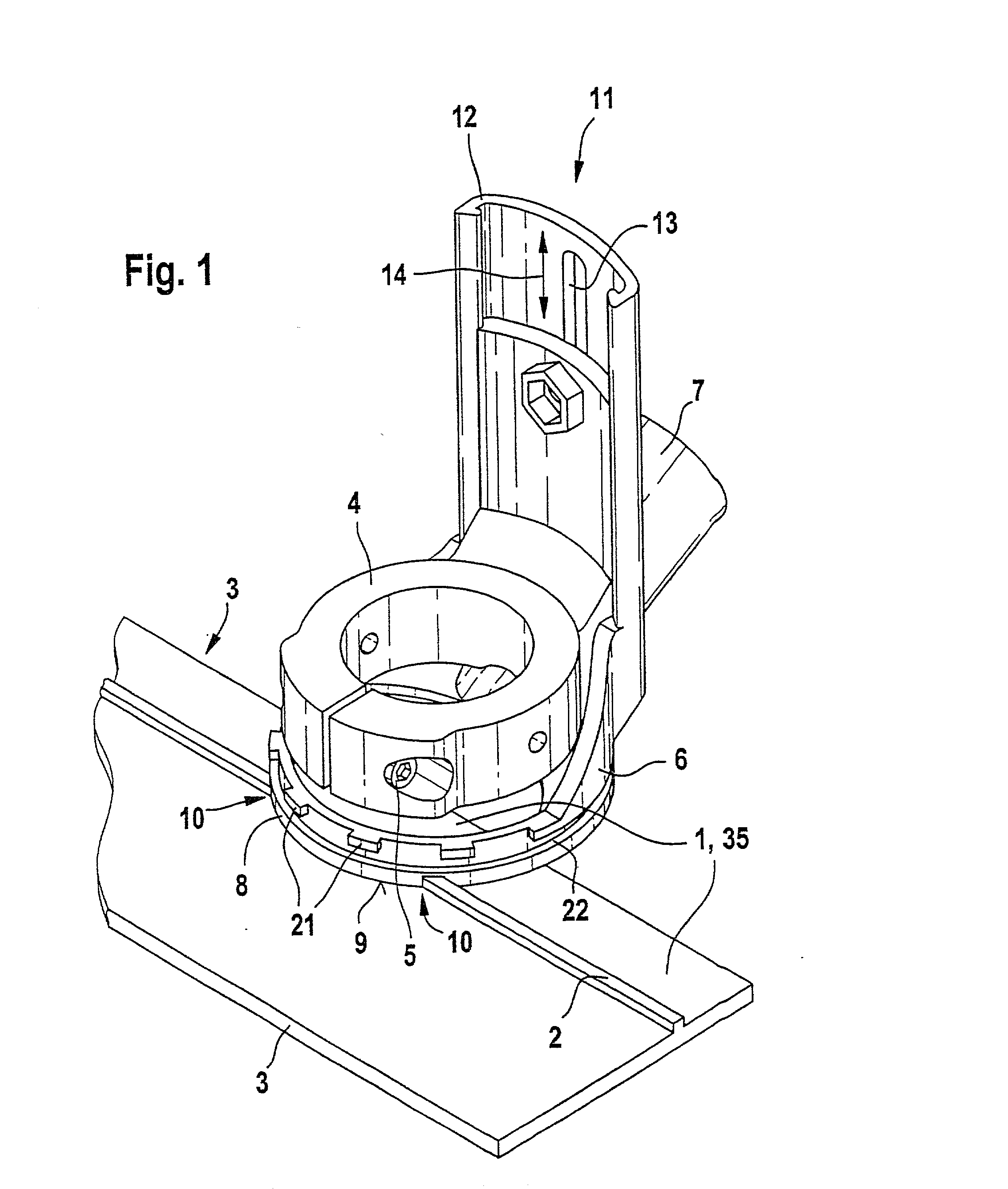
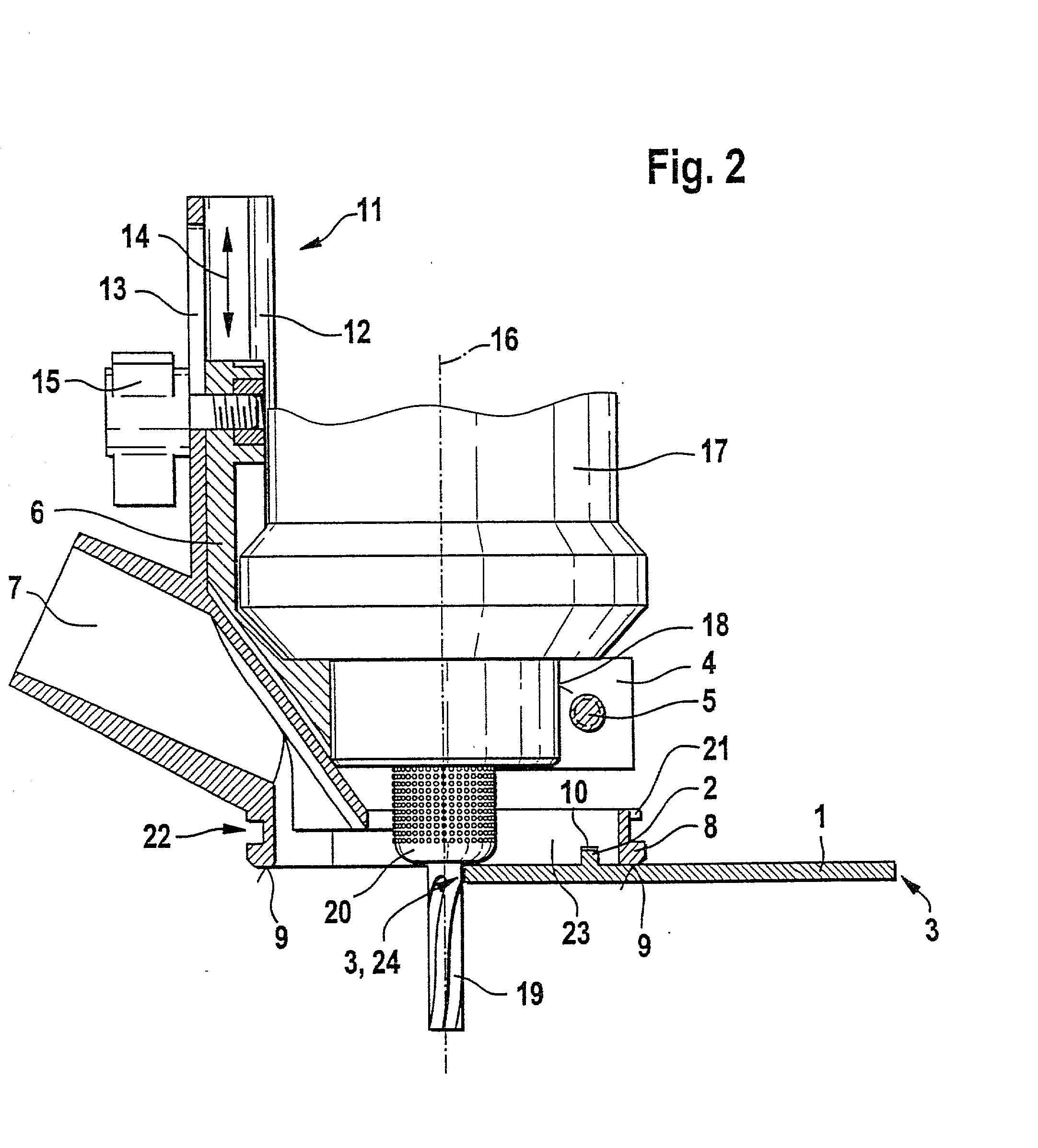
[0018] From FIG. 1, a perspective view of a bearing face mounted on a guide rail with a guide rib can be seen, which is received on an extension in which a clamping ring that receives the electric power tool is displaceable vertically.

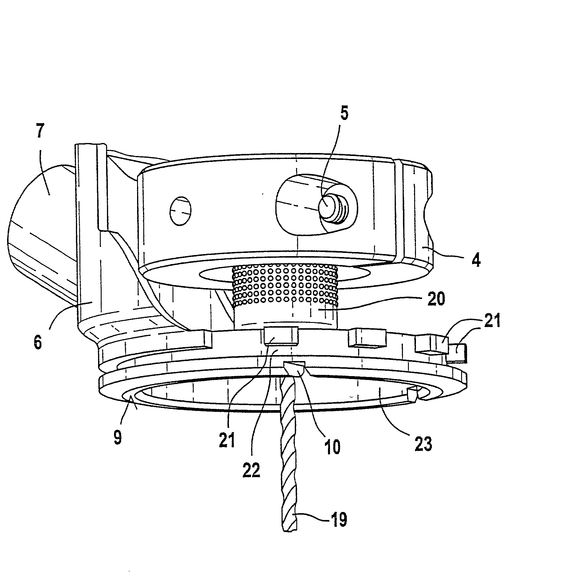
[0019] The guide rail identified by reference numerals 1, 35 is provided with a guide rib 2 extending parallel to the length of the guide rail 1, 35. The guide rib 2 is raised above the surface of the guide rail 1, 35. The guide rail 1, 35 is bounded on both sides by edges 3. The electric power tool, not shown in the perspective view of FIG. 1, is surrounded by a seat face 18 of the clamping ring 4, and the prestressing in the clamping ring 4 is generated by a clamping screw 5. The clamping ring 4 is displaceable in a guide profile 12 in the vertical direction indicated by the double arrow 14, and the relative position between the continuation of the clamping ring 4 and the guide profile 12 can be defined by means of a longitudinal groove 13 and an act...


PUM

PropertyMeasurementUnit
Thicknessaaaaaaaaaa
Heightaaaaaaaaaa
Circumferenceaaaaaaaaaa

Abstract

The invention relates to an electric power tool with a housing, in which a drive mechanism is received; the electric power tool includes a shaft, with a chuck (20) received in it, for receiving a tool insert (19). The chuck (20) is surrounded by an annular bearing face (9). The bearing face (8, 9) includes receiving elements that enable the guidance of the electric power tool on a guide rail (1, 35), such as receptacles (21, 22; 31, 32) and (33) for slip-on tools (25), such as templates, that can be received on the support (8, 9).

Description

[0001] Electric power tools both for do-it-yourselfers and for craftsmen must be suitable for many different purposes, if they are to find enough customers. For the most various purposes of the electric power tool, retrofitting of the electric power tool may be needed from one intended use to another, and as much as possible such retrofitting should be feasible without an additional tool. Besides retrofitting that can be done quickly and simply on the tool and is preferably feasible via snap closures or bayonet mounts, there is a need on an electric power tool to be able to move the electric power tool along a guide as well, to enhance the quality of the work done, such as the course of a cut or the location of a milled opening.PRIOR ART[0002] Copying sleeves used until now, which can be used as slip-on tools on electric power tools, require a complicated receptacle on the bearing foot of the tool. If the slip-on tool for instance is copying sleeves, then when used in interior compl...

Claims


Application Information

Patent Timeline
IPC IPC(8): B23B45/14B23C5/26B23Q7/10B23Q9/00B23Q35/10B23Q35/42B25F3/00
CPCB23Q7/10B23Q9/0014B23Q35/104B23Q35/42Y10T409/304088Y10T409/308624Y10T409/306608Y10T409/303472Y10T409/303696Y10T409/306384Y10T409/306496
Inventor BERGNER, JOAOENGELFRIED, UWENOACK, MARTIN
Owner ROBERT BOSCH GMBH
Why Eureka
Try Eureka