Tension assisted ankle joint and orthotic limb braces incorporating same

Inactive Publication Date: 2002-12-12
TOWNSEND INDUSTRIES INC
View PDF0 Cites 40 Cited by
  • Summary
  • Abstract
  • Description
  • Claims
  • Application Information

AI Technical Summary

Problems solved by technology

Some individuals are afflicted with a condition that does not permit the individual to have full control over muscles that raise and lower the foot.
Such a condition poses substantial difficulty when walking.
As a result, the individual may end up dragging the foot or may find themselves tripping when walking.
Therefore, the individual may stumble and fall while

Method used


Image

  • Tension assisted ankle joint and orthotic limb braces incorporating same
  • Tension assisted ankle joint and orthotic limb braces incorporating same
  • Tension assisted ankle joint and orthotic limb braces incorporating same

Examples


Embodiment Construction

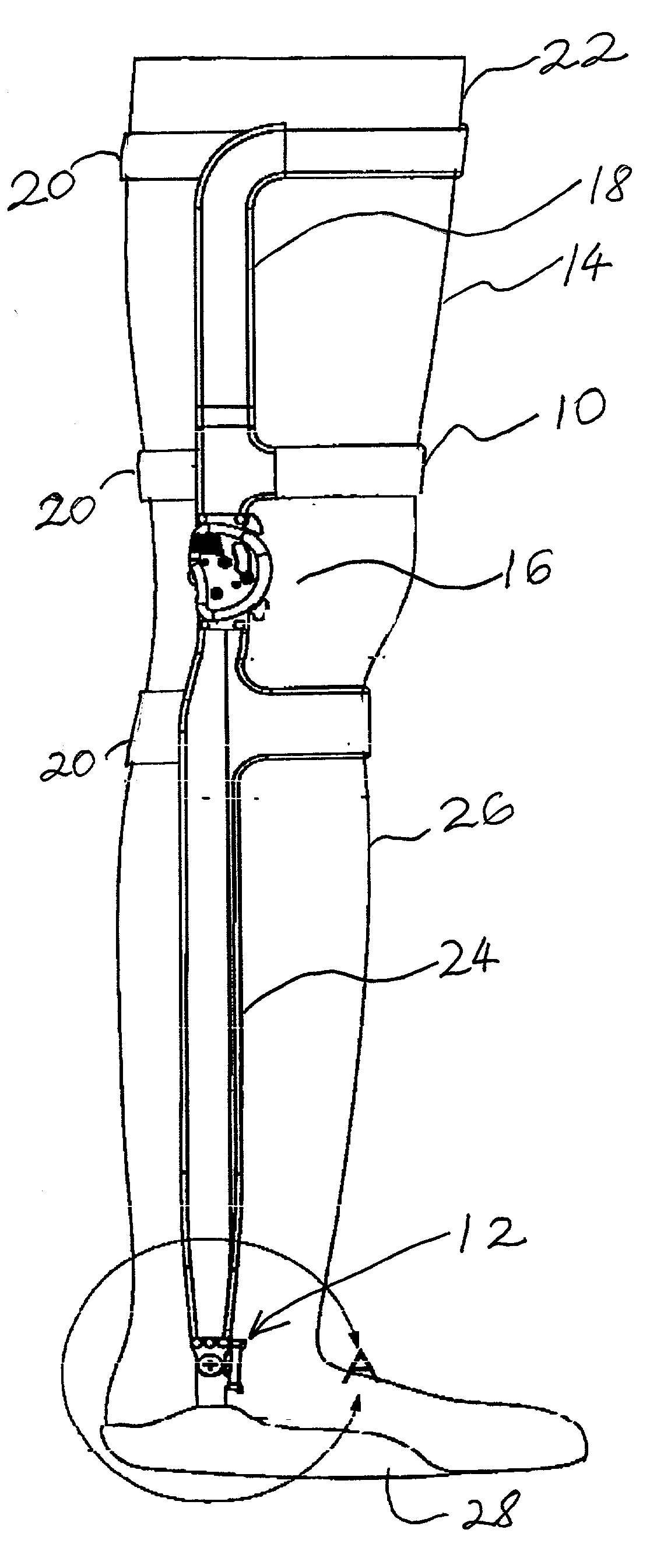
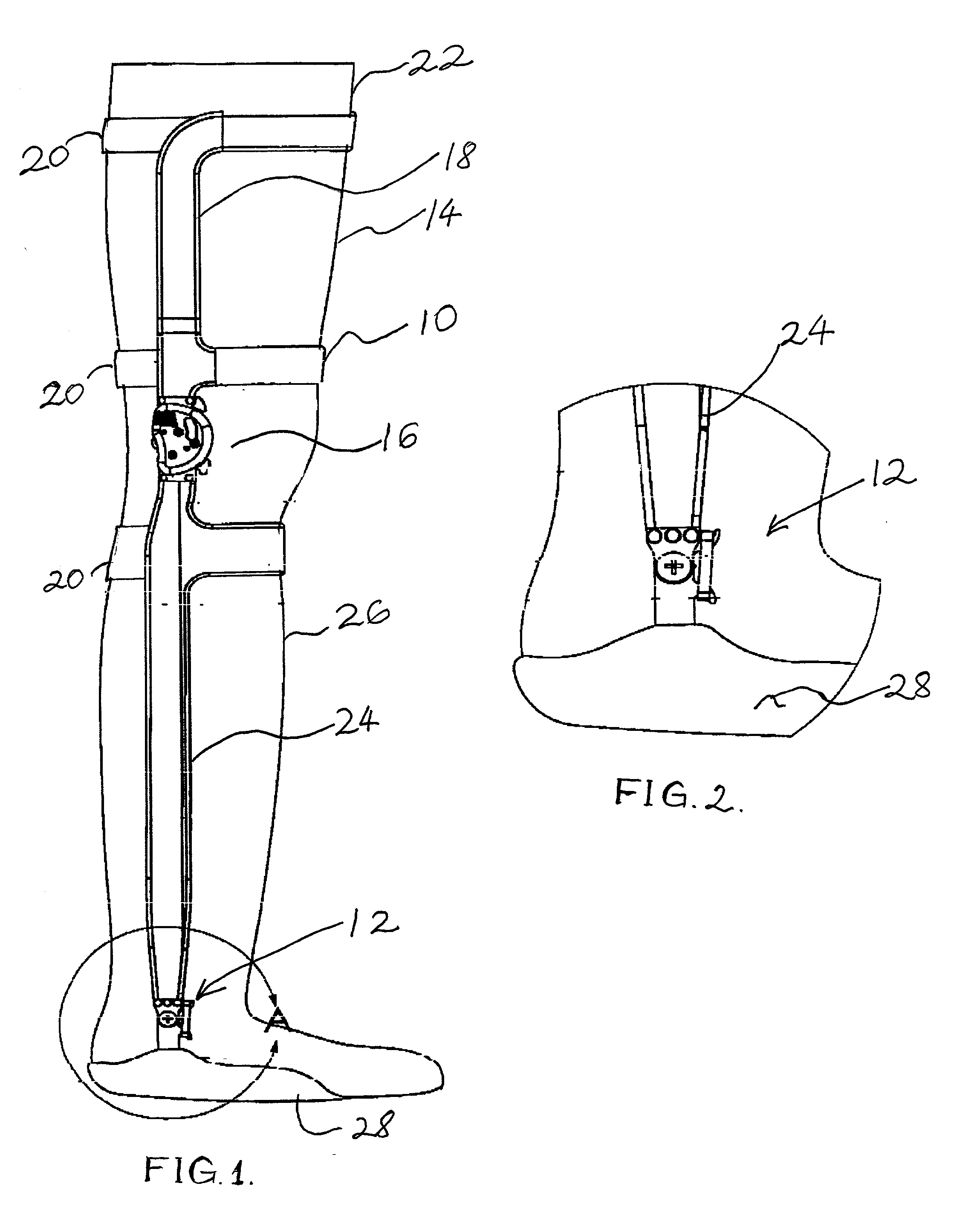
[0024] FIG. 1 shows a knee ankle foot orthosis (KAFO) 10 that incorporates a first exemplary embodiment of a joint 12 in accordance with the invention being worn by a patient 14. The KAFO 10 has a solid core graphite shell that result in a rigid, durable bracing solution that achieves effective and consistent control. The KAFO 10 is ultra light, extremely low profile and exceptionally comfortable.

[0025] The KAFO 10 includes a second joint 16 positioned proximate to the knee and may also incorporate the features of the invention. However, joint 16 may be of known design as well, such as those disclosed in U.S. Pat. Nos. 4,773,404; 4,890,607; 5,259,832; 5,330,418; and 5,743,418 and commonly owned, co-pending U.S. patent application Ser. No. 09 / 694,484.

[0026] FIG. 2 shows an enlarged detail view of the joint 12. The KAFO includes a thigh shell 18 and two straps or bands 20 holding the thigh shell 18 to the thigh 22 of the patient 14. The KAFO also includes a below knee shell 24 which i...


PUM


Abstract

An improved limb brace joint includes a band that operates in tension to rotationally bias first and second longitudinal members of the joint. The band of the joint biases the rotation of the members to provide a dorsiflexion and/or plantarflexion assist when used in an ankle foot orthosis.

Description

[0001] 1. Field of the Invention[0002] The present invention is directed to the art of orthotic limb brace joints. In particular, the invention is directed to an improved limb brace joint that rotationally biases the limbs of the wearer.[0003] 2. Description of Related Art[0004] Patients with physical conditions or injuries sometimes require the use of an orthotic limb brace, such as an ankle foot orthosis (AFO) or knee ankle foot orthosis (KAFO). These orthoses aid several functions in ambulation, including control of dorsiflexion and plantarflexion in both the stance and swing phases of gait. AFOs also stabilize the ankle in the frontal and transversal planes during balance and gait activities.[0005] Some individuals are afflicted with a condition that does not permit the individual to have full control over muscles that raise and lower the foot. One condition for which an individual does not have full control over the muscles is known as "drop foot". "Drop foot" occurs when the i...

Claims


Application Information

Patent Timeline
IPC IPC(8): A61F5/01
CPCA61F5/0125A61F2005/0179A61F5/0127
Inventor TOWNSEND, JEFFREYKNECHT, STEVE
Owner TOWNSEND INDUSTRIES INC
Why Eureka
Try Eureka