Linearly actuated locking device for transit vehicle door system

a technology for transit vehicles and locking devices, which is applied in the direction of electrical locking circuits, wing accessories, lock applications, etc., can solve the problems of unsatisfactory increase in preload forces acting on the door lock mechanism, system complex locks with numerous failure points,

Inactive Publication Date: 2003-01-02
WESTINGHOUSE AIR BRAKE TECH CORP
View PDF14 Cites 17 Cited by
  • Summary
  • Abstract
  • Description
  • Claims
  • Application Information

AI Technical Summary

Benefits of technology

0014] Still another object of the present invention is to provide a simple lock for a transit vehicle which locks the door(s) in a pushback mode so a passenger may open the door(s) slightly to remove a limb, garment portion or the like from the closed door(s).
0015] Yet, another object of the present invention is to provide a simple lock for a transit vehicle which utilizes simple linear actuators for locking and unlocking door(s).
0016] An additional object of the present invention is to provide a simple lock for transit vehicle having means to bias door(s) in the locked position.
0017] Yet an additional object of the present invention is to provide a simple lock for transit vehicle having means to manually unlock door(s).

Problems solved by technology

Furthermore, in cases where excessive traffic loads exist, passengers may be pressing against the doors thereby resulting in an undesirable increase in preload forces acting on the door lock mechanism.
Many prior art door systems have quite complex locks which exhibit numerous failure points.

Method used


Image

  • Linearly actuated locking device for transit vehicle door system
  • Linearly actuated locking device for transit vehicle door system
  • Linearly actuated locking device for transit vehicle door system

Examples


Embodiment Construction

, particularly, when the detailed description is taken in conjunction with the attached drawing figures and with the appended claims.

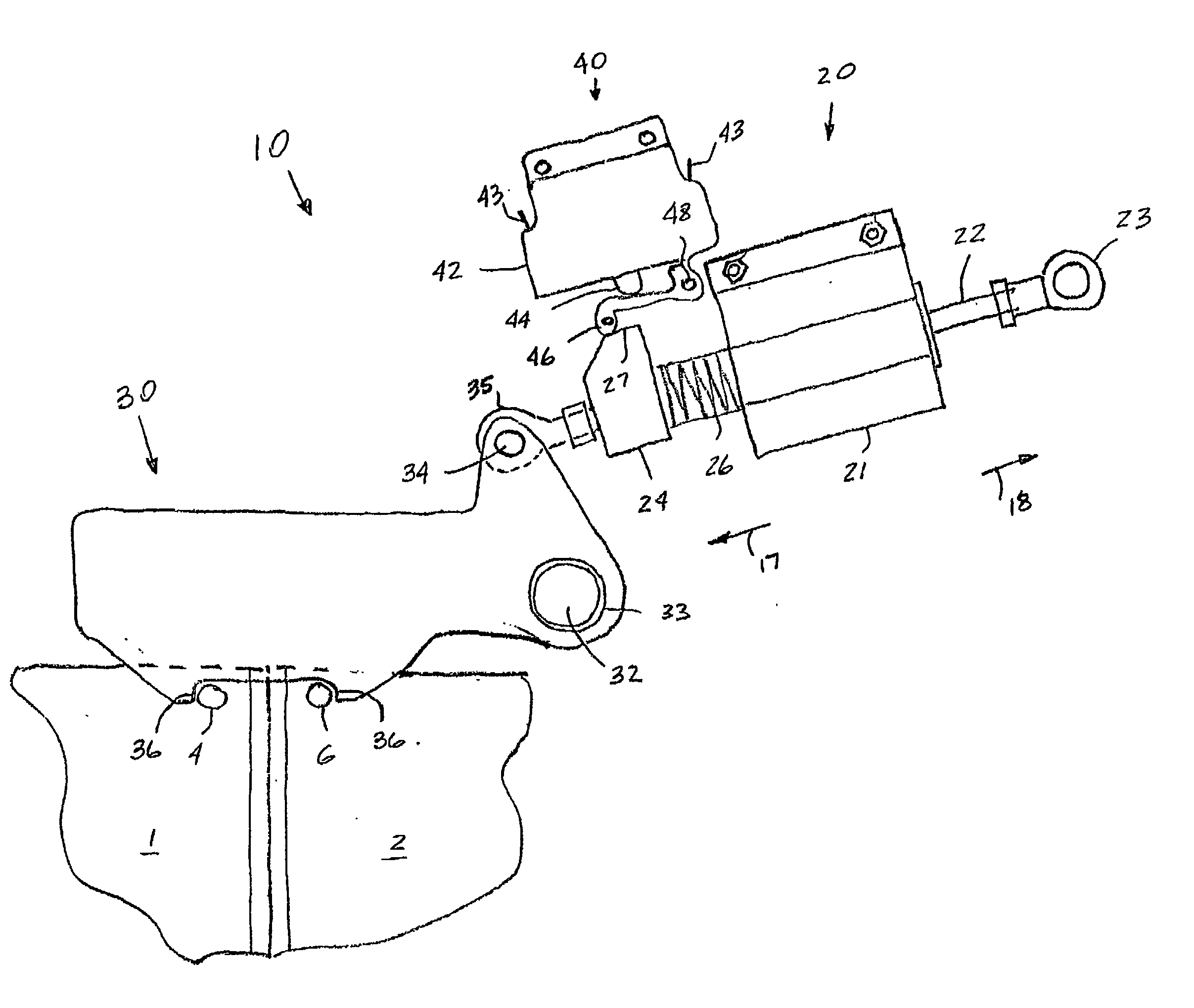
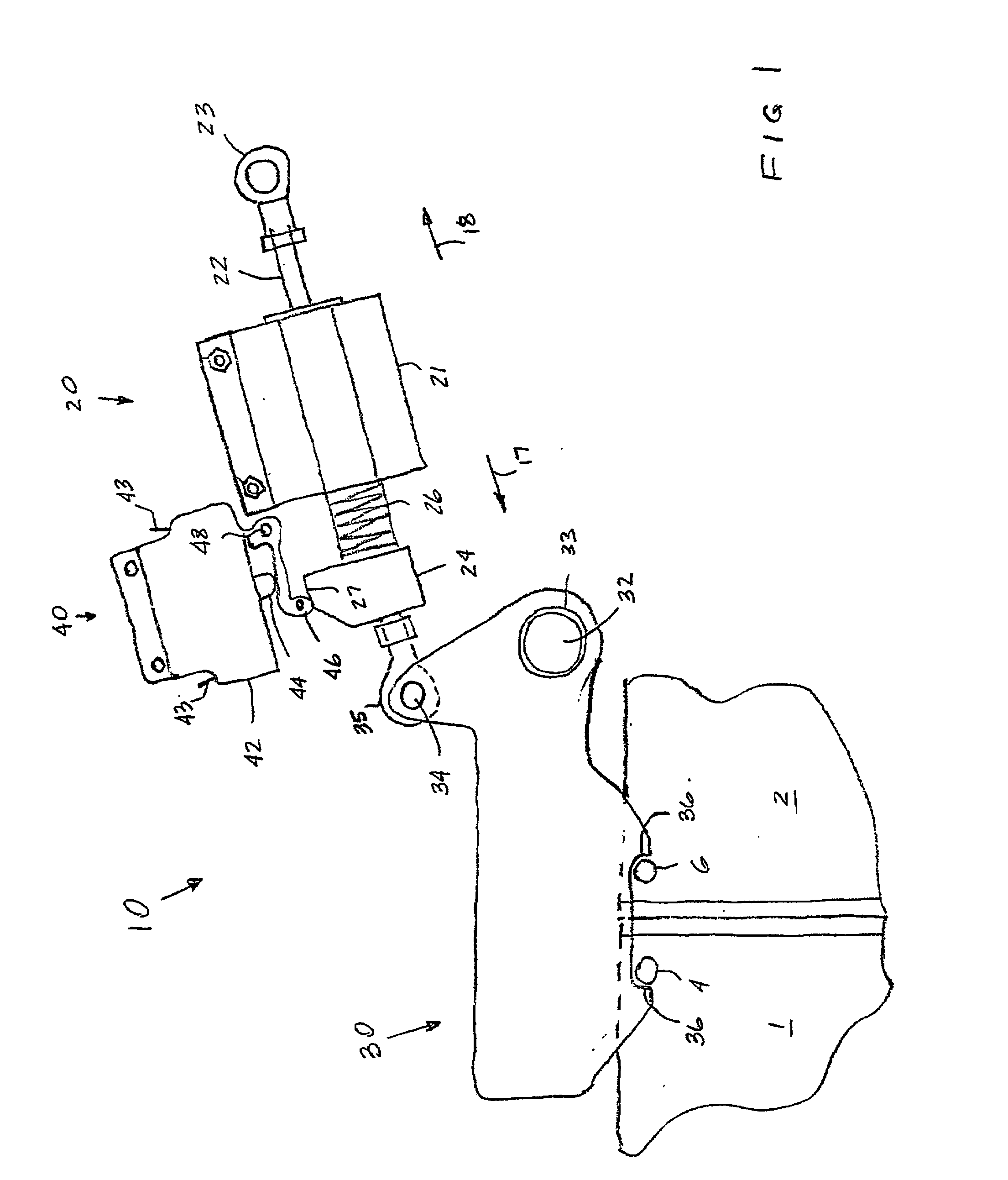
[0019] FIG. 1 is a pictorial view of a locking device for locking transit vehicle door in a closed position.

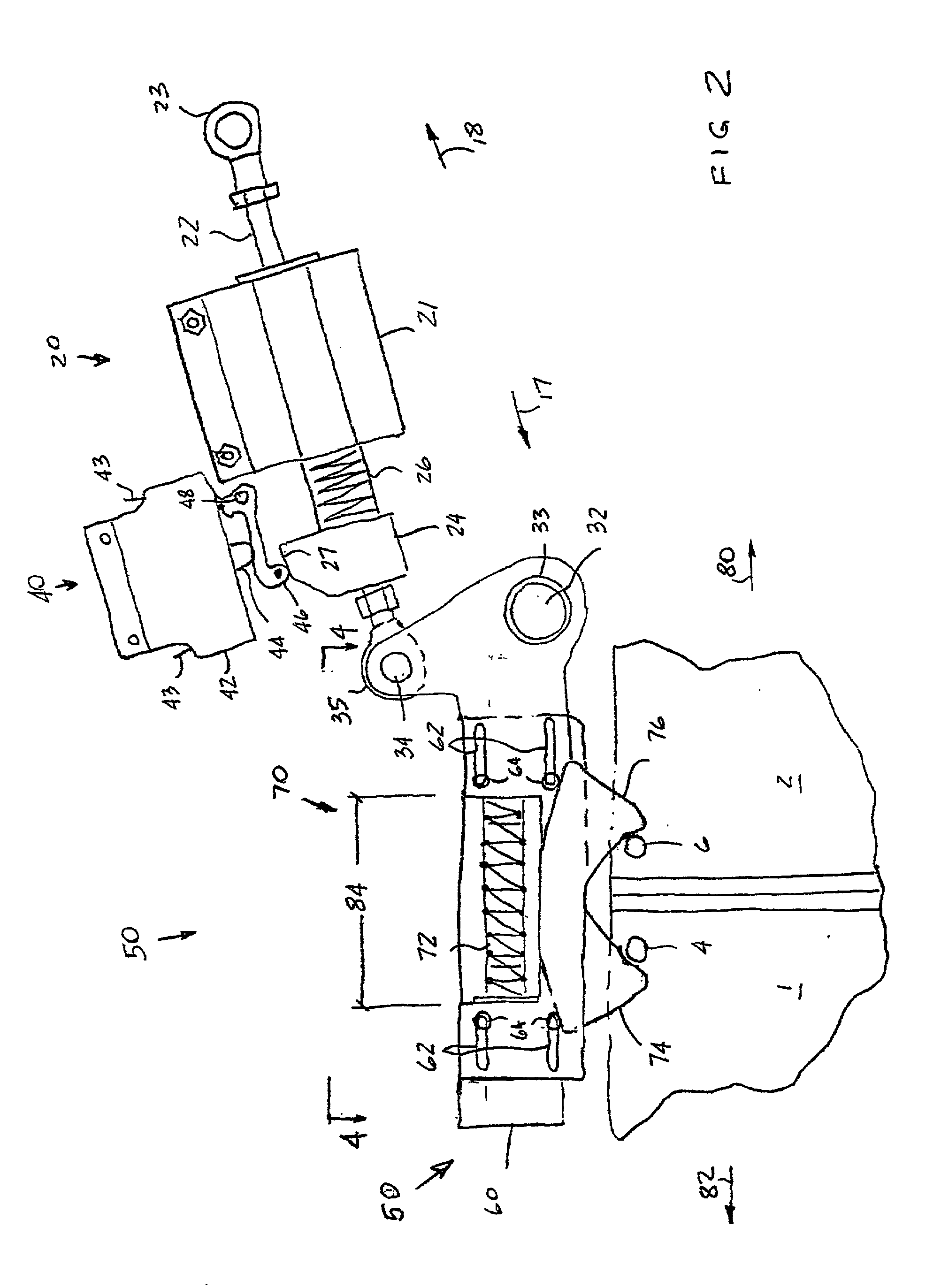
[0020] FIG. 2 is a pictorial view of a locking device for locking transit vehicle doors in a pushback lock position.

[0021] FIG. 3 is a pictorial view of the crossover of a pair of latches for the locking device of FIG. 2.

[0022] FIG. 3 is the horizontal view of the present invention taken along the lines 4-4 of FIG. 2 showing disposition of the wear spacers and guide pins.

BRIEF DESCRIPTION OF THE PRESENTLY PREFERRED AND VARIOUS ALTERNATIVE EMBODIMENTS OF THE INVENTION

[0023] Prior to proceeding to the more detailed description of the instant invention, it should be noted that identical components which have identical functions have been identified with identical reference numerals throughout the several views illustrated in the drawing figures for ...


PUM


Abstract

A locking device for attachment to a fixed portion of a transit vehicle door system is for locking one or more doors of the transit vehicle door system in either a fully locked position or a pushback lock position. The locking device has a simple lock arm, biased toward the locking position and rotatably attached to the fixed portion of the transit vehicle door system at a first pivot of the rotary lock arm, the rotary lock arm having at least one door engagement portion for engaging a portion of the door(s) for locking the door(s) when the rotary lock arm is in at least one of the locking position and the pushback position thereof. A linear actuator, rotating the lock arm to the unlocked position when energized, is attached to the fixed portion of the transit vehicle door system and connected to a second pivot of the lock arm, said second pivot offset from the first pivot. A lock actuator sensing switch provides a feedback on the actuator position to the transit vehicle control system. Means are provided within linear actuator to manually rotate lock arm toward unlocked position for opening doors during an emergency.

Description

[0001] The invention taught in this patent application is closely related to the invention taught in the following co-pending U.S. Provisional Patent Application Serial No. 60 / 271,350 and was filed on Feb. 23, 2001. All the teachings therein are incorporated into this application by reference thereto.[0002] The present invention relates, in general, to transit vehicle door systems and, more particularly, the instant invention relates to linearly actuated transit vehicle door locks having a pushback feature.[0003] Door locks for transit vehicles are a major operational concern, particularly, to the mass transit industry. These door locks must provide a fail-proof system for locking of the door panel in the event of a door mechanism failure. This is required in order to prevent unintentional opening movement of such doors which would permit a passenger to fall out of the vehicle when it is in motion. Nevertheless, these doors must allow for normal door movement upon receipt of the leg...

Claims


Application Information

Patent Timeline
Patent Type & Authority Applications(United States)
IPC IPC(8): E05B17/00E05B47/00E05B47/02E05B51/02E05B63/00E05B65/00E05B65/08E05B65/12E05B65/36E05B77/50E05C7/00
CPCE05B17/007E05B83/42E05B47/023E05B63/0069E05B65/0003E05B65/0811E05B65/0829E05B77/00E05B77/46E05B77/50E05C2007/007E05B81/64E05B83/363E05B81/10E05B83/40E05B47/0002
Inventor OAKLEY, ROBERT L.PAYNE, ROBERT
Owner WESTINGHOUSE AIR BRAKE TECH CORP
Why Eureka
Try Eureka