
Method and system for identifying a tyre of a vehicle

Inactive Publication Date: 2003-01-02
TRW AUTOMOTIVE ELECTRONICS & COMPONENTS GMBH & CO KG
View PDF5 Cites 20 Cited by
  • Summary
  • Abstract
  • Description
  • Claims
  • Application Information

AI Technical Summary

Benefits of technology

[0012] Proceeding from this, the invention is intended to provide a method and a system which render possible, without time-consuming and cost-intensive recalibration, unambiguous identification of tyres of a vehicle and unambiguous identification of sensor signals, relating to the corresponding tyres, measured at the tyres. Furthermore, the invention is intended to provide a solution which avoids the need to use additional devices (e.g., transponders, long-wave transmission units) for the calibration operation. In addition, malfunctions of a tyre pressure monitoring system are to be reduced, and corrected in a simple manner.SHORT DESCRIPTION OF THE INVENTION
[0017] In addition, it is possible to measure and compare with one another the tyre pressure of all tyres at which tyre pressures have been measured. Analysis of the tyre pressures can then be performed using information which comprises the previously recorded tyre pressures or tyre pressure variations, reference tables and information used for the application of neural networks or chaos-theory methods. In this way, the identification of the individual tyres of the vehicle can be performed more rapidly and with greater exactness, since not only driving state parameters, but also information resulting from the comparison of the tyre pressures of all wheels is used for analysing the at least one pressure variation. This additional information permits a more accurate description of the driving-dynamic state of the vehicle in which the tyre pressures are determined. Moreover, there is a reduction of the number of different driving-dynamic states of the vehicle in which tyre pressures of the tyres have to be measured in order for individual tyres of the vehicle to be unambiguously identified.
[0019] In addition, the method can also comprise a measurement of driving state parameters that are determined by driving-dynamic states of the vehicle. In this way, it is no longer necessary for the required driving state parameters to be provided by other components of the vehicle which perform corresponding methods for measuring driving state parameters. The measurement of driving state parameters can also be thus optimised, in that the measurement of the driving state parameters is specially adapted to the identification of tyres.
[0021] Furthermore, data can be stored which is used for identifying individual tyres or all tyres of the vehicle. This data for identifying tyres can be used during the operation of the vehicle, so that it is not necessary to repeat performance of the method according to the invention for identifying tyres.

Problems solved by technology

The recalibration of such tyre pressure monitoring systems is time-consuming and requires additional facilities for activating the transponders assigned to the individual pressure sensor elements.
If, nevertheless, a tyre change is performed without recourse to a specialist vehicle firm, i.e., if it is performed privately or if no calibration operation is performed when a tyre is changed, faultless functioning of the tyre pressure monitoring system is no longer assured.
Moreover, malfunctions of the tyre pressure monitoring system can occur if, for example, the tyre pressure monitoring system can no longer be provided with the current assignment.
This can occur, for example, if a memory in which the current assignment is stored is inadvertently / accidentally erased.
In any case, the operation of the vehicle has to be interrupted, since the recalibration of the tyre pressure monitoring system cannot be performed independently / automatically by the latter and / or during the driving operation of the vehicle.
A disadvantage in this case is that, in addition to the components for measuring the tyre pressures, it is necessary for components to be located on the tyres or wheels and on the vehicle for the purpose of transmitting the long-wave signals, as well as generating the long-wave identification signals, embedding them in the data signals and extracting them from the data signals again following their transmission.

Method used


Image

  • Method and system for identifying a tyre of a vehicle
  • Method and system for identifying a tyre of a vehicle

Examples


Embodiment Construction

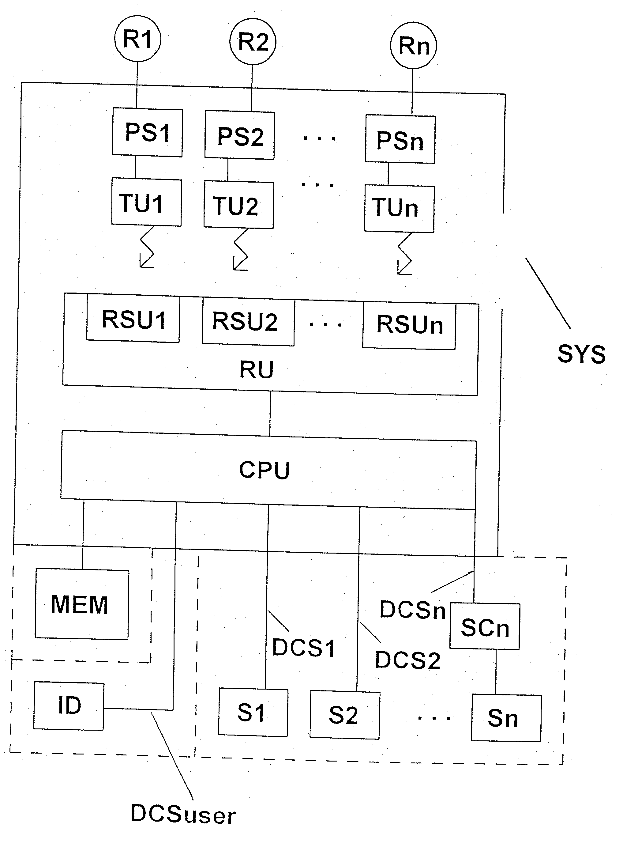
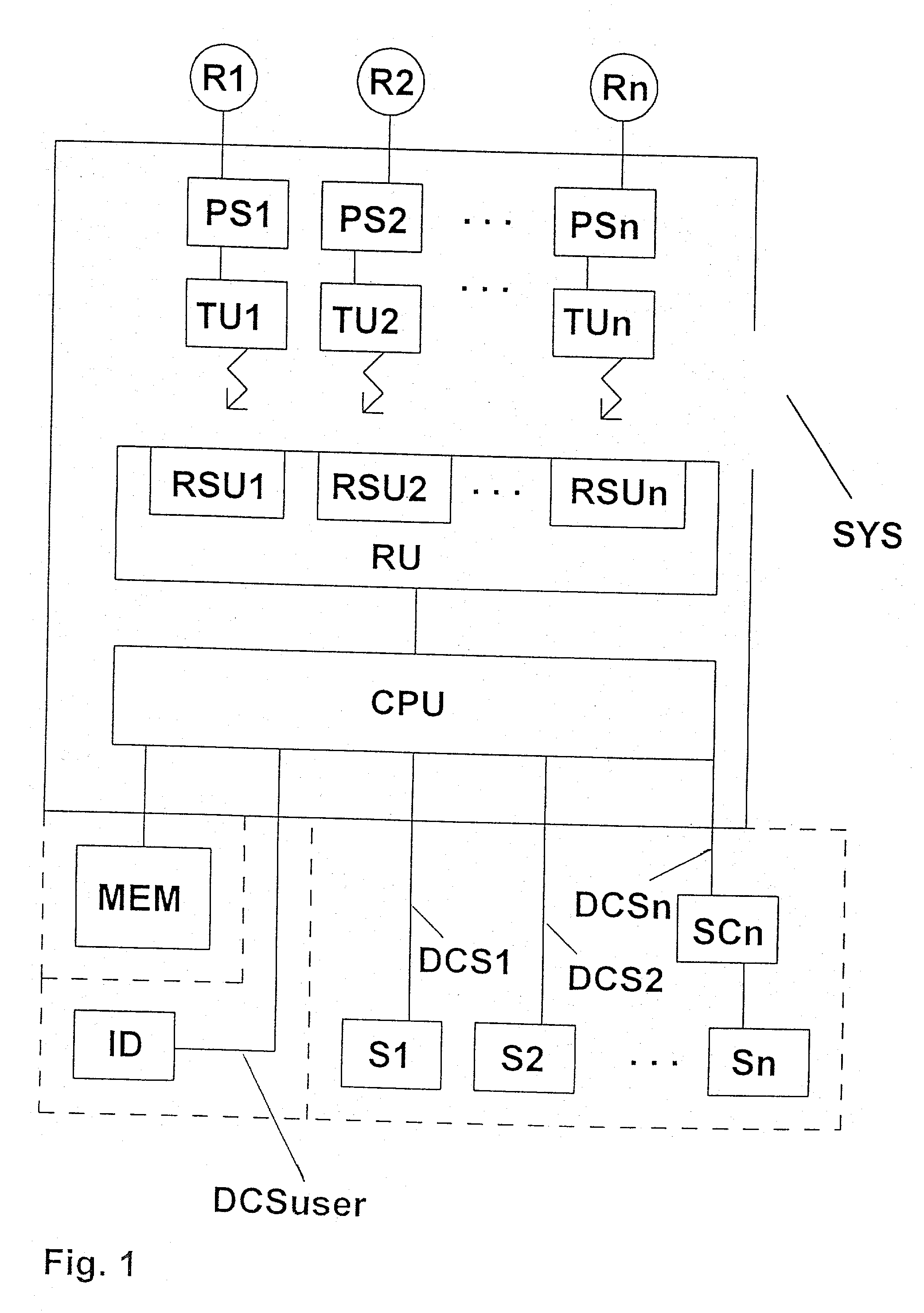
[0033] As shown in FIG. 1, the system SYS for identifying a tyre R1, . . . , Rn of a vehicle comprises pressure sensors PS1, . . . , PSn which are respectively assigned to one of the tyres R1, . . . , Rn of the vehicle for the purpose of measuring the corresponding tyre pressure. Each pressure sensor PS1, . . . , PSn is connected to a transmitting device TU1, . . . , TUn for the purpose of transmitting to the transmitting devices TU1, . . . , TUn signals which indicate the respective measured tyre pressure.

[0034] Depending on the type of sensor, the tyre pressure signals from the pressure sensors PS1, . . . , PSn can be analog or digital signals. The transmitting devices TU1, . . . , TUn transmit the received tyre pressure signals or corresponding signals to a receiver device RU. The tyre pressure signals are transmitted by wireless transmission from the individual transmitting devices TU1, . . . , TUn to the receiver device. It may therefore be necessary for the transmitting device...


PUM


Abstract

The invention concerns a method and a system for identifying tyres of a vehicle, tyre pressures of the tyres of the vehicle being measured and analysed for the driving-dynamic states of the vehicle with the use of parameters which indicate the driving-dynamic states. Individual tyres of the vehicle are unambiguously identified on the basis of the analysis of the measured tyre pressures or their variations.

Description

DESCRIPTION[0001] 1. Background of the invention[0002] The invention concerns a method and a system for measuring and processing driving-dynamic parameters of a vehicle. In particular, the invention concerns a method and a system for identifying a tyre of a vehicle by using the tyre pressures of the tyres to be identified.[0003] 2. Prior art[0004] Known systems for monitoring tyre pressures of different tyres of a vehicle comprise pressure sensor elements which are normally mounted on the rims and are surrounded by the corresponding tyres, or are mounted on the insides of the tyres, or are integrated into the tyres or the valve. The pressure sensor elements are respectively connected to a transmitter by which both the signals / data indicating the measured tyre pressures and an identification (ID information) which is characteristic of the corresponding pressure sensor elements are transmitted to a receiver. The receiver evaluates both the signals / data indicating the tyre pressures an...

Claims


Application Information

Patent Timeline
IPC IPC(8): B60C23/04
CPCB60C23/0416
Inventor SCHMITT, HUBERT
Owner TRW AUTOMOTIVE ELECTRONICS & COMPONENTS GMBH & CO KG
Learn More