
Method and apparatus for assisted GPS

a technology of assisted gps and method, applied in the field of radio communication systems, can solve the problems of insufficient to meet fcc requirements, limited precision of this technique, and limited mobile station location determination capability of current radio communication generations

Inactive Publication Date: 2003-01-16
GOOGLE TECH HLDG LLC
View PDF10 Cites 166 Cited by
  • Summary
  • Abstract
  • Description
  • Claims
  • Application Information

AI Technical Summary

Problems solved by technology

Current generations of radio communication have only limited mobile station location determination capability.
However, the precision of this technique is limited and, at times, may be insufficient to meet FCC requirements.
Thus, the computational load for performing the traditional calculation is significant.
Such processors are relatively expensive and consume large amounts of power.
These design goals are inconsistent with the high computational load required for GPS processing.
Further, the slow data rate from the GPS satellites is a limitation.
The long GPS acquisition time can rapidly deplete the battery of a mobile station.
In any situation and particularly in emergency situations, the long GPS acquisition time is inconvenient.
The location accuracy of the three GPS modes of operation can degrade substantially when undetected GPS satellite failures are present: such failures, though rare, can render the positioning information derived by a mobile handset completely unusable.
Although the GPS Control Segment monitors the health of the GPS satellites, this activity is not performed continuously, and may require more than 30 minutes to be communicated to GPS users.
In addition, for A-GPS operating in a differential mode, unexpected multipath at the DGPS receiver surveyed site can lead to larger than nominal location errors, independent of the health of the GPS constellation.

Method used


Image

  • Method and apparatus for assisted GPS
  • Method and apparatus for assisted GPS
  • Method and apparatus for assisted GPS

Examples


Embodiment Construction

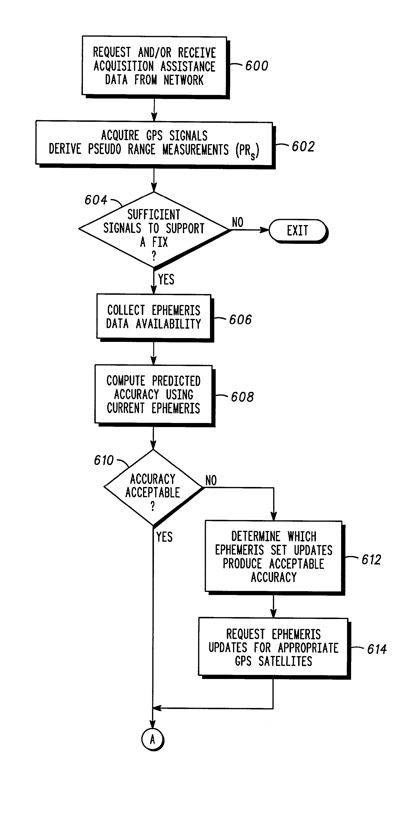
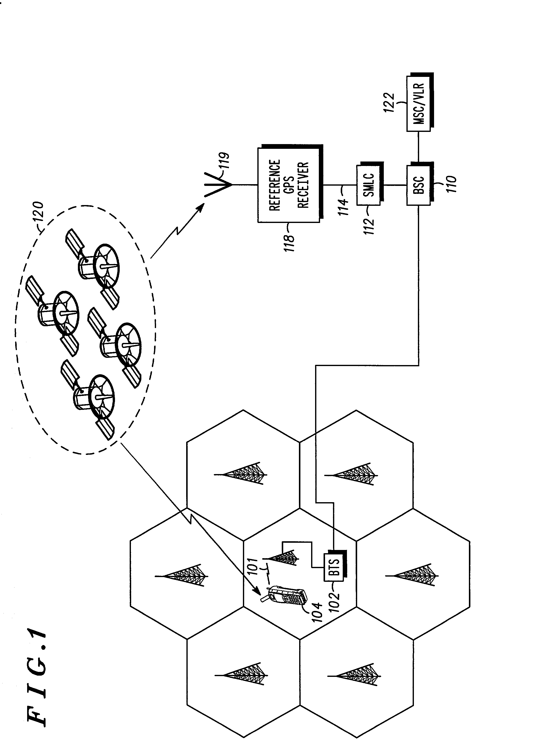
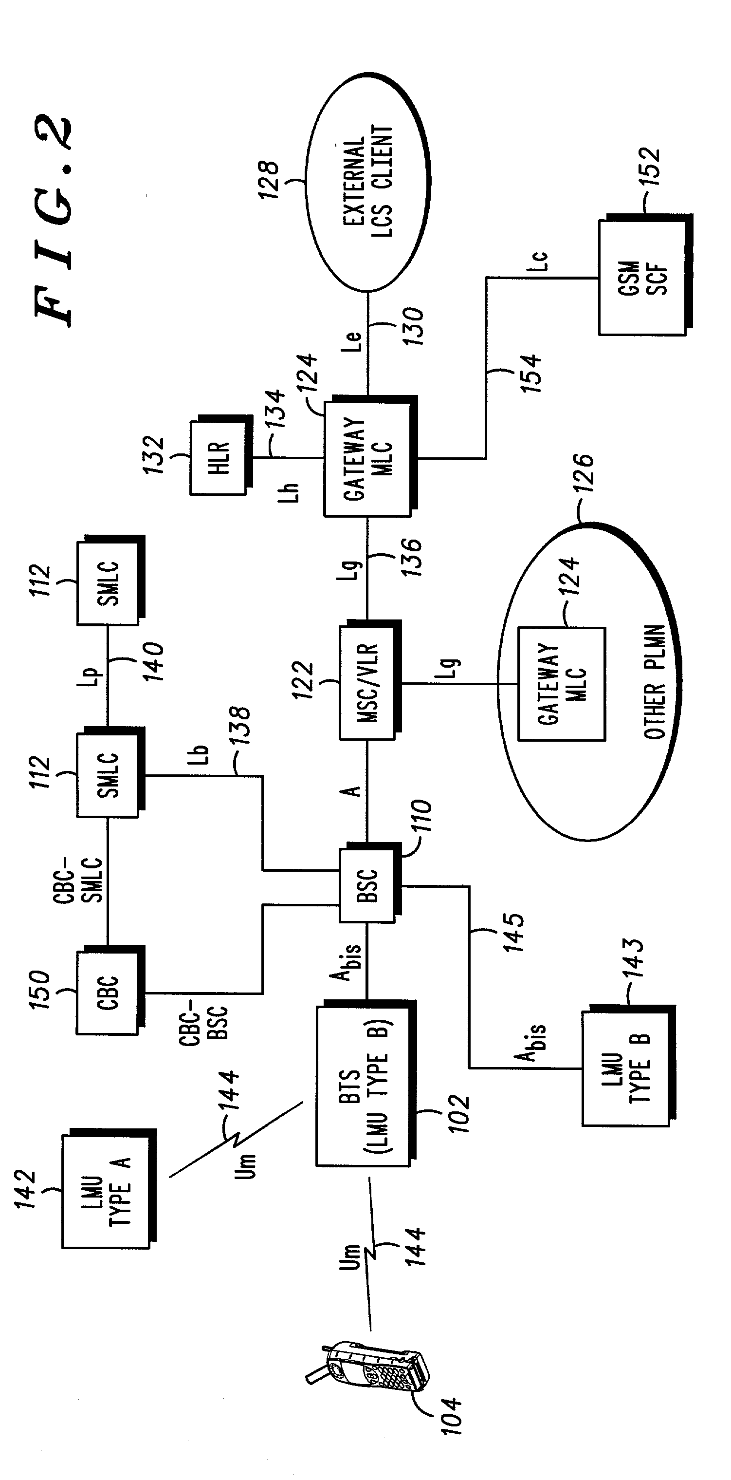
[0029] An improved system and method of Assisted GPS receiver location determination and integrity maintenance are described. The system of the present invention includes novel architectures, which can determine mobile station location with a high degree of accuracy and tolerance of off-nominal error conditions. Referring to FIG. 1, as an application example, a GSM cellular network is depicted utilizing the system diagram of an Assisted GPS location system in accordance with the preferred embodiment of the present invention. This is a system with a Base Station Subsystem (BSS)-based Serving Mobile Location Center (SMLC) 112. The reference GPS receiver 118 is located at a surveyed location with SMLC 112 and has an open view of the sky in order to facilitate generation of appropriate assistance and corrections data. In this architecture, it implies that the GPS server is an integral part of the SMLC 112. Alternatively, this server cold also be an integral part of the reference GPS rec...


PUM


Abstract

A cellular network protocol that maintains the reliability of assisted GPS based positioning is taught. An Integrity Monitor (IM) informs mobile stations, their users, or networks of measurement quality and it warns them of failing and failed GPS satellites by isolating them from the effects of these failures. Whenever an unhealthy satellite is detected, its corresponding assistance data will be excluded for delivery or for position determination. In other words, there are two specific aspects to the Integrity Monitor (IM). For DGPS users, it predicts the reliability or quality of the DGPS corrections. For all users, it isolates the mobile position calculation from the effects of GPS satellite failures. The UDRE parameter, nominally output by a reference DGPS receiver, is used to communicate the DGPS quality information, and DGPS corrections are simply excluded for failed satellites. For autonomous GPS users, a special integrity message is required and defined to communicate the satellite failure status information.

Description

[0001] The present application is a divisional application of U.S. application Ser. No. 09 / 480,380 filed on Jan. 10, 2000, which is continuation-in-part of prior U.S. application Ser. No. 09 / 438,204, filed on Nov. 11, 1999, now U.S. Pat. No. 6,363,787, all of which are incorporated herein by reference, and from which priority is claimed.FIELD OF THE INVENTIONS[0002] The present inventions relate generally to radio communication systems, and more particularly to methods and apparatuses for maintaining the integrity of mobile handset location determination in a radio communication system, and methods therefor.BACKGROUND OF THE INVENTIONS[0003] Radio communication systems generally provide two-way voice and data communication between remote locations. Examples of such systems are cellular and personal communication system (PCS) radio systems, trunked radio systems, dispatch radio networks, and global mobile personal communication systems (GMPCS) such as satellite-based systems. Communi...

Claims


Application Information

Patent Timeline
Patent Type & Authority Applications(United States)
IPC IPC(8): G01C21/00G01S19/27G01S1/00G01S5/00G01S5/14G01S19/07G01S19/08G01S19/20H04Q7/34H04Q7/38
CPCG01S5/0045G01S5/009G01S19/05G01S19/07G01S19/08G01S19/20G01S19/235G01S19/256G01S19/258G01S5/14H04W4/02G01S19/071
Inventor KING, THOMAS M.GEIER, GEORGE J.ZHAO, YILIN
Owner GOOGLE TECH HLDG LLC
Learn More