Umbrella shaft, and umbrella having such an umbrella shaft

a technology which is applied in the field of umbrella shaft and umbrella shaft, can solve the problems of difficulty in handling the block and tackle, and difficulty in stowing away the rope of the block and tackl

Inactive Publication Date: 2003-01-23
GLATZ AG
View PDF14 Cites 56 Cited by
  • Summary
  • Abstract
  • Description
  • Claims
  • Application Information

AI Technical Summary

Benefits of technology

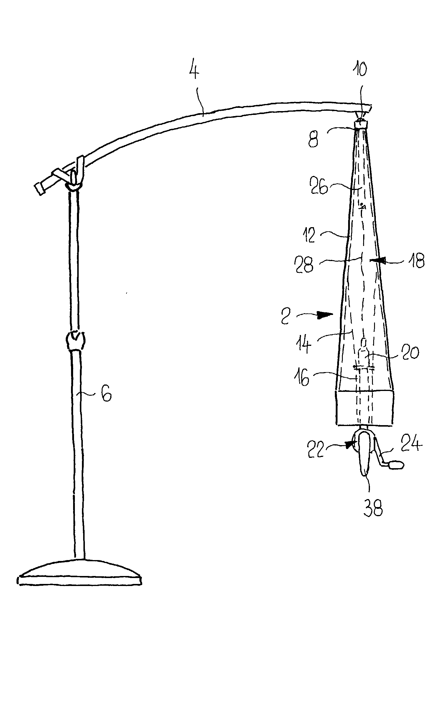
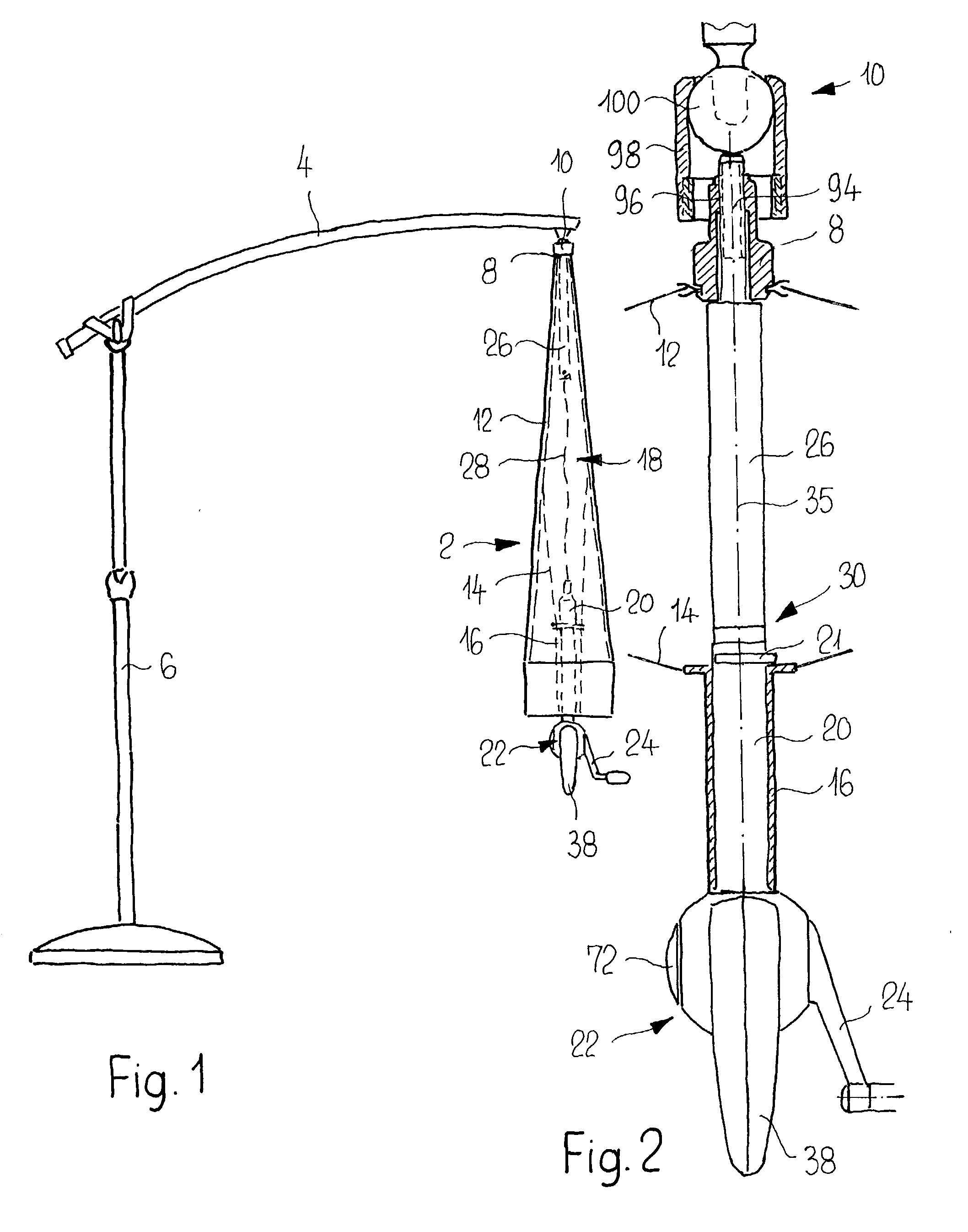
[0007] Since the rope drive is designed as a rope winch which can be connected to the slide, and since the rope runs coaxially with the shaft axis, this provides a drive which is easily accessible, is easy to operate and, furthermore, blends in harmoniously with the design of the umbrella. In particular the rope is accommodated in a protected manner in the umbrella shaft, with the result that laborious stowage operations are dispensed with and there is no adverse effect on the appearance of the open umbrella. Moreover, such an umbrella shaft makes it possible to have an umbrella which can be removed from an extension arm without the rope connection also having to be released. Moreover, the umbrella shaft does not obstruct the extension arm from being extended and retracted.
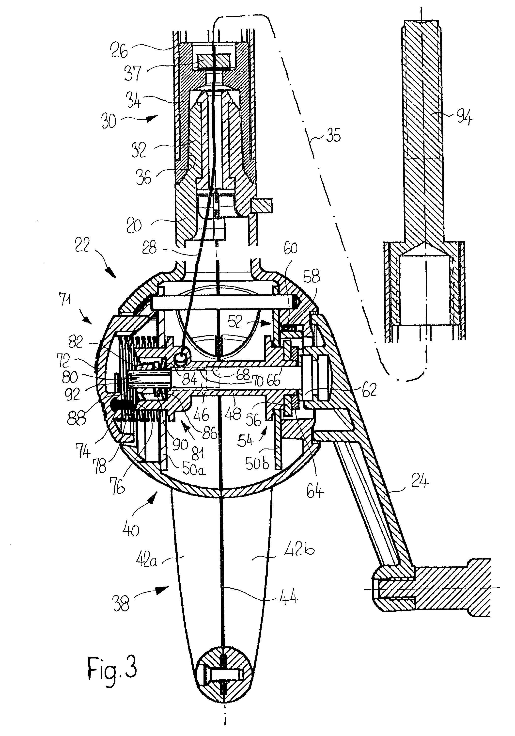
[0010] The configuration of the umbrella shaft according to claim 16, with the handle, is particularly advantageous, in particular in the annular development thereof according to claim 17, since the handle makes it easier to grip the slide, and thus the rope winch, without the user first having to reach into the umbrella and open the latter some way beforehand. The handle also makes it easier to operate the rope winch with the hand crank. The annular handle in particular, in addition, covers the hand crank when the latter is oriented downward, as a result of which, on the one hand, the hand crank is protected against damage and, on the other hand, the user is protected against being injured by a projecting hand crank. The handle, furthermore, may perform an additional operating function for transporting a torque, in order for example for the shaft part, according to claim 18, to be screwed into a crown of the umbrella, and interact with a ball-and-socket joint, by way of a threaded bolt, in order to block or release said ball-and-socket joint.
[0011] The umbrella shaft may be configured as an independent component and serve for subsequent installation or the exchange of an umbrella shaft in an existing umbrella, in order, in the case of such an umbrella, to eliminate the disadvantages mentioned in the introduction and achieve advantages. However, it is also possible for an umbrella to be equipped directly with the umbrella shaft according to the invention.

Problems solved by technology

The block and tackle is awkward to handle, the accessibility being rendered more difficult, in particular in the case of relatively large umbrellas in the closed state of the umbrella.
Moreover, the block and tackle is exposed, with the result that the lengths of rope of the block and tackle are difficult to stow away when the umbrella is open and have an adverse effect on the appearance of the open umbrella.
This opening operation is very laborious in the case of large umbrellas in particular since relatively large forces are necessary and, furthermore, the accessibility is made more difficult.
Such an umbrella, although easy to handle, cannot be removed from the extension arm, as is the case with the abovementioned umbrellas, without the rope connection having to be released.

Method used


Image

  • Umbrella shaft, and umbrella having such an umbrella shaft
  • Umbrella shaft, and umbrella having such an umbrella shaft
  • Umbrella shaft, and umbrella having such an umbrella shaft

Examples


Embodiment Construction

[0005] The object of the invention is to provide an umbrella shaft of the type mentioned in the introduction which makes it possible to improve hanging umbrellas.

[0006] This object is achieved according to the invention by the features of claims 1 and 19.

[0007] Since the rope drive is designed as a rope winch which can be connected to the slide, and since the rope runs coaxially with the shaft axis, this provides a drive which is easily accessible, is easy to operate and, furthermore, blends in harmoniously with the design of the umbrella. In particular the rope is accommodated in a protected manner in the umbrella shaft, with the result that laborious stowage operations are dispensed with and there is no adverse effect on the appearance of the open umbrella. Moreover, such an umbrella shaft makes it possible to have an umbrella which can be removed from an extension arm without the rope connection also having to be released. Moreover, the umbrella shaft does not obstruct the extens...


PUM


Abstract

Umbrella shaft for a hanging umbrella, having a shaft part (20,26) and a rope drive (22), which connects a slide (16) and a crown (8) of the umbrella, the slide and the shaft part being coupled axially to one another when the umbrella is open. In order to improve the operability, the rope drive is designed as a rope winch (22) which can be connected to the slide (16), the rope (28) running essentially coaxially with the axis of the umbrella shaft.

Description

[0001] The invention relates to an umbrella shaft according to the preamble of claim 1 and to an umbrella according to claim 19.PRIOR ART[0002] An umbrella shaft or an umbrella of the type mentioned in the introduction is known, for example, from CH-A-661 189, the rope drive comprising a block and tackle which is arranged between the slide and the crown of the umbrella. The block and tackle is awkward to handle, the accessibility being rendered more difficult, in particular in the case of relatively large umbrellas in the closed state of the umbrella. Moreover, the block and tackle is exposed, with the result that the lengths of rope of the block and tackle are difficult to stow away when the umbrella is open and have an adverse effect on the appearance of the open umbrella.[0003] CH-A-367 290 and 666 166 disclose umbrellas which are each hung in a removable manner on an extension arm by means of a ball-and-socket joint, the extension arm extending transversely to a stand. The umbre...

Claims


Application Information

Patent Timeline
Patent Type & Authority Applications(United States)
IPC IPC(8): A45B23/00A45B25/14
CPCA45B23/00A45B25/14A45B2023/0012A45B2023/0037A45B2025/146
Inventor GLATZ, GUSTAV ADOLF
Owner GLATZ AG
Why Eureka
Try Eureka