
Calender and process for operating a calendar

a calender and calendar technology, applied in the field of calender and process operation of calender, can solve the problems of virtually unavoidable vibration in calender, unusable paper web, waste of paper rolls, etc., and achieve the limitation of the service life of such a roll

Inactive Publication Date: 2003-02-06
VOITH PATENT GMBH
View PDF9 Cites 3 Cited by
  • Summary
  • Abstract
  • Description
  • Claims
  • Application Information

AI Technical Summary

Benefits of technology

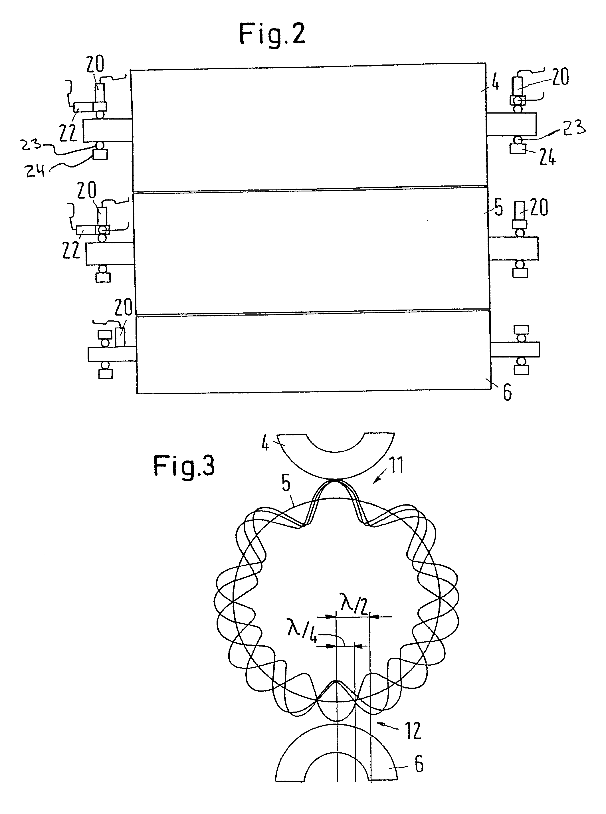
[0017] A wavelength that corresponds to an integral fraction of the circumference of a roll preferably exists for each preset frequency. When the barring patterns on the surface of a roll are analyzed, it is established that this is a wave pattern in which the wavelength corresponds to an integral fraction of the roll circumference. It will not be possible to observe barring patterns with other wavelengths, because with these other barring patterns a transforming would have to result continuously which prevents a final development of such a barring pattern. In the case of barring patterns in which an integral multiple of the wavelength yields exactly the circumference of the roll, this erasing does not occur. However, a certain frequency can be assigned to each of these barring patterns, which frequency also depends, e.g., on the circumferential speed of the relevant roll. In this way, it is relatively simple to calculate the preset frequencies.
[0018] The vibration is preferably determined at least on each middle roll, and the preset frequencies are restricted to wavelengths that occur on the corresponding roll. This approach has several advantages. For one thing, the vibration that occurs on a roll can be detected directly from this roll with substantially lower damping than on other rolls. The information on the roll vibration is therefore more directly available. For another, a substantially smaller number of preset frequencies has to be taken into consideration. This applies in particular when the rolls of the roll stack feature different circumferences. However, this situation occurs as a rule in particular when one or more rolls with elastic coatings have already been reworked once. In this case, the processing costs are reduced, as only less information needs to be evaluated. The regulation can then be made more quickly.
[0026] The vibration recording device is preferably arranged at least on each middle roll. The vibrations are therefore determined on each middle roll. This has the advantage that for one thing the vibration of each middle roll can be determined on the middle roll itself, so that it has not been damped or even falsified by a transmission path via other rolls. Furthermore, the evaluation can be restricted to the critical frequencies which can occur at the specific roll. Finally, when the vibration is determined individually on each roll, at least on each middle roll, a step can be taken in a more targeted manner to prevent the development of a barring pattern on each roll.
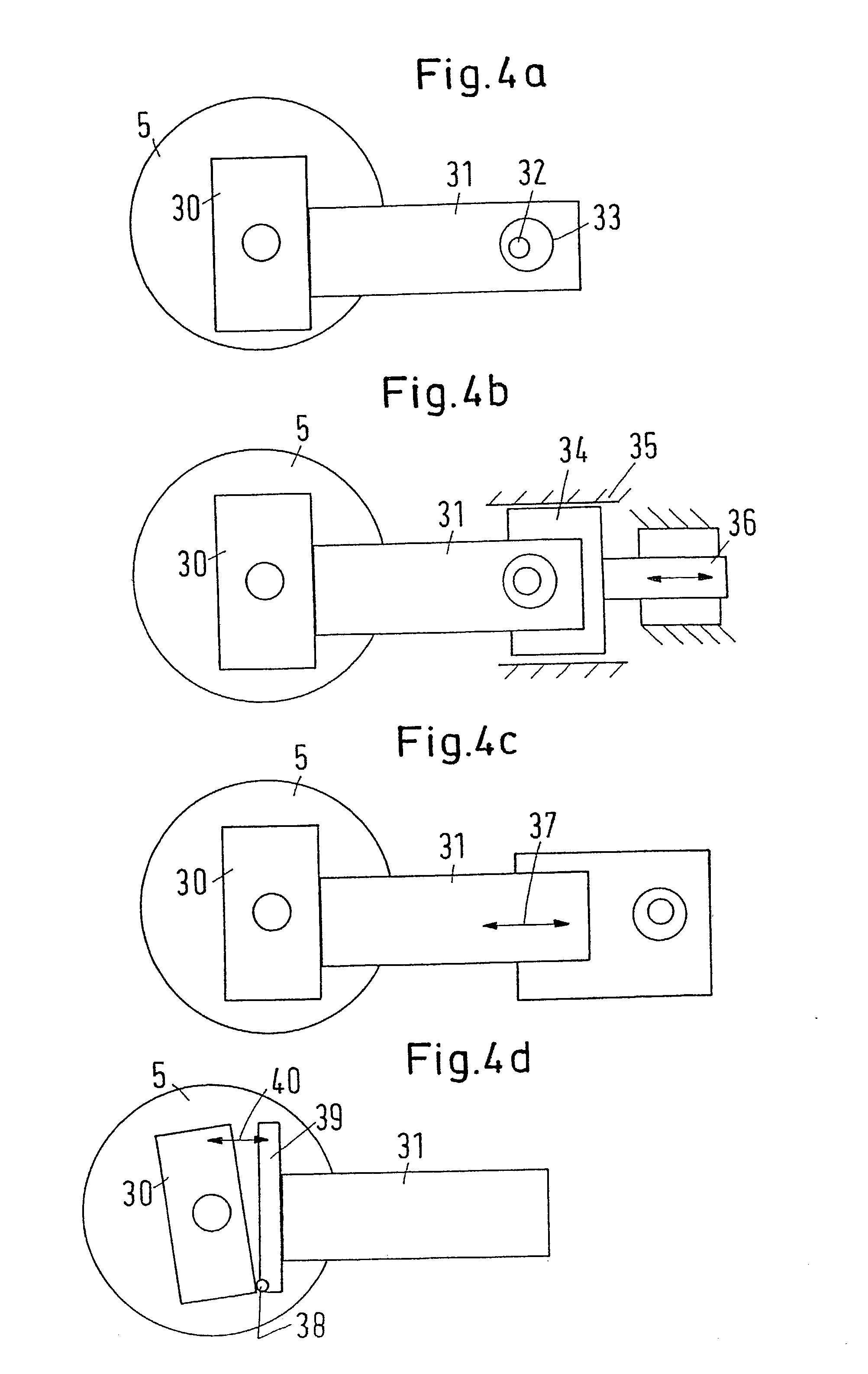
[0027] At least the middle rolls are preferably arranged on levers and the adjustment drive acts on the lever. This is a relatively simple measure to effect the displacement of the respective roll perpendicular or cross-wise to the press direction.
[0032] In a further alternative embodiment there can be provided a hinged connection with a tilting gearing to be provided between the lever and a bearing housing. Displacement movements of the roll can thereby be adjusted relatively precisely.

Problems solved by technology

However, it can be used in the same way with other material webs with which similar problems occur.
As soon as these stripes become visible, the paper web is unusable and forms waste.
However, vibrations are virtually unavoidable in a calender.
The service life of such a roll is therefore limited.
In addition, a paper web is never free from basis weight or thickness fluctuations.
These resonance points cannot be constructively avoided because of the large number of possible exciters and the large number of possible natural shapes of vibrations.
This results in a regeneration of the vibration.
Some days or weeks usually pass until this phenomenon has grown so significantly that it disrupts the production process.
Although this runs the risk of barring patterns developing, the operation of the calender is changed less frequently, keeping further possibilities for disruption to a minimum.
It will not be possible to observe barring patterns with other wavelengths, because with these other barring patterns a transforming would have to result continuously which prevents a final development of such a barring pattern.
In the case of longer differences in distance, the roll would have to be displaced further accordingly, whereby the risk of achieving an unfavorable change in the geometry of the roll stack would have to be taken into account.

Method used


Image

  • Calender and process for operating a calendar
  • Calender and process for operating a calendar
  • Calender and process for operating a calendar

Examples


Embodiment Construction

[0044] The particulars shown herein are by way of example and for purposes of illustrative discussion of the embodiments of the present invention only and are presented in the cause of providing what is believed to be the most useful and readily understood description of the principles and conceptual aspects of the present invention. In this regard, no attempt is made to show structural details of the present invention in more detail than is necessary for the fundamental understanding of the present invention, the description taken with the drawings making apparent to those skilled in the art how the several forms of the present invention may be embodied in practice.

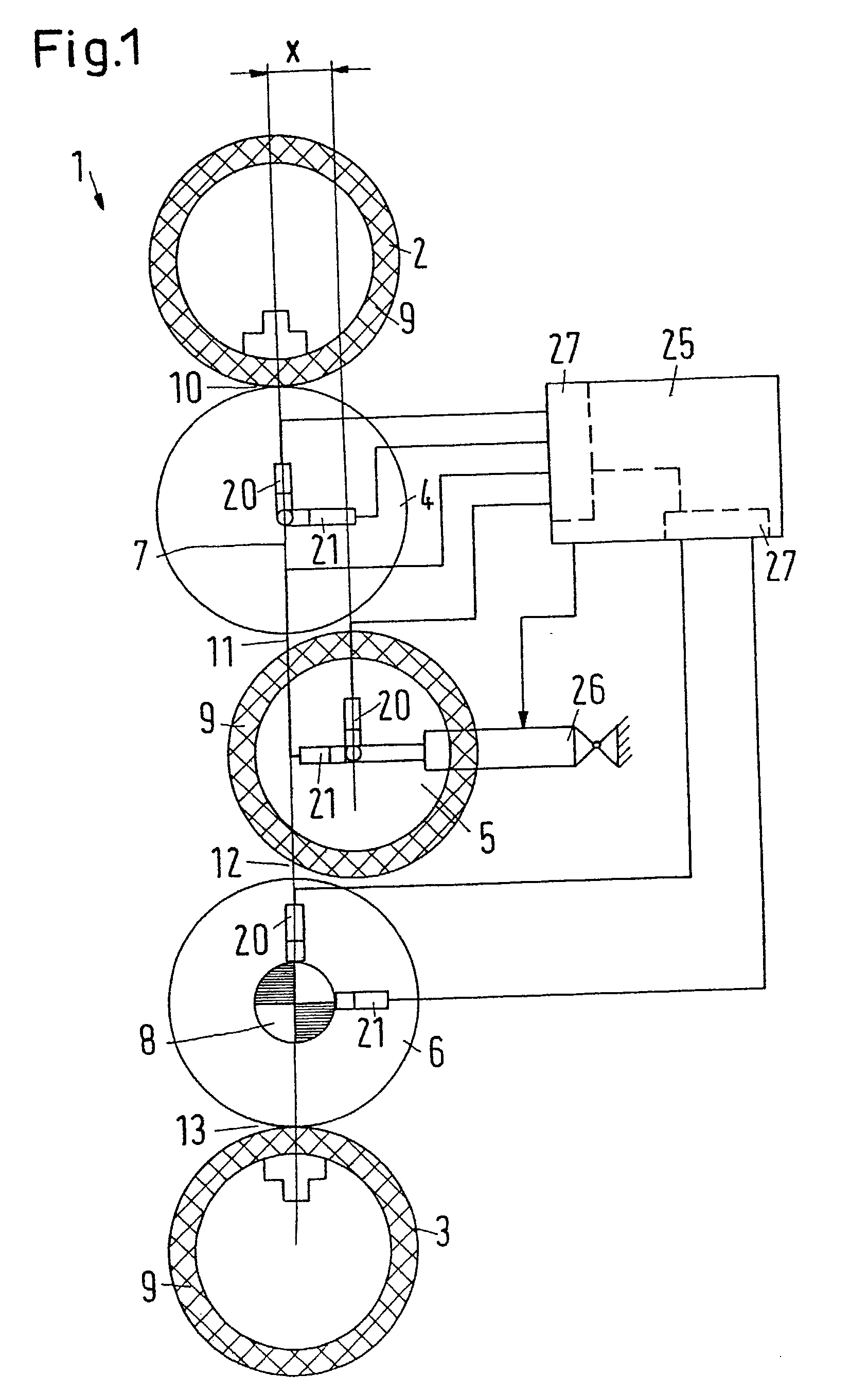
[0045] FIG. 1 shows a diagrammatic representation of a calender 1 with two end rolls 2, 3 that are embodied as load-deflection rolls, and three middle rolls 4-6 that together form a roll stack. The roll stack features a roll plane 7 in which the axes of all rolls 2-6 lie when the rolls 2-6 are arranged exactly one above ...


PUM

PropertyMeasurementUnit
Lengthaaaaaaaaaa
Distanceaaaaaaaaaa
Circumferenceaaaaaaaaaa

Abstract

Calender including a roll stack having a plurality of rolls that rest against one another in a press direction. At least one of the rolls has an elastic surface. A vibration recording device determines in an uninterrupted manner a vibration of at least one of the rolls. A mechanism displaces the at least one roll crosswise to the press direction based on the vibration. The process includes determining in an uninterrupted manner a vibration of at least one of the rolls and displacing the at least one roll crosswise to the press direction based on the vibration.

Description

[0001] The present application claims priority under 35 U.S.C. .sctn.119 of German Patent Application No. 101 33 888.0, filed on Jul. 12, 2001, the disclosure of which is expressly incorporated by reference herein in its entirety.[0002] 1. Field of the Invention[0003] The invention relates to a process for operating a calender with a roll stack which features two end rolls and in between several middle rolls that rest against one another in a press direction, with at least one roll having an elastic surface. The invention further relates to a calender with a roll stack which features two end rolls and in between several middle rolls, with at least one roll having an elastic surface.[0004] 2. Discussion of Background Information[0005] Such calenders are used in particular for glazing paper or cardboard webs. The invention is described below on the basis of the treatment of a paper web. However, it can be used in the same way with other material webs with which similar problems occur....

Claims


Application Information

Patent Timeline
IPC IPC(8): D21G1/00
CPCD21G1/00D21G1/008
Inventor VAN HAAG, ROLFSCHEIDELER, EVAWOLF, ROBERT
Owner VOITH PATENT GMBH
Learn More