
Distributed fiberoptic sensors

a fiberoptic sensor and fiber optic technology, applied in the field of sensing devices, can solve the problems of not providing real-time dose information, irregular or incomplete curing of parts, and inability to ensure that each current batch of parts is correctly cured

Inactive Publication Date: 2003-02-06
HRL LAB
View PDF0 Cites 5 Cited by
  • Summary
  • Abstract
  • Description
  • Claims
  • Application Information

AI Technical Summary

Benefits of technology

[0019] Devices according to the present invention may achieve the desired functionality, and also have further advantages. Sensors according to the present invention are formed of very thin optical fiber, and readily fit many shapes needed for complex molded parts. Individual sensor fibers, with the appropriate sensing electronics to interpret the results, can sense one or more types of radiation at one or more regions of the single fiber. In some embodiments, radiation may be qualitatively indicated by direct optical output laterally from the sensor.

Problems solved by technology

When molded parts having complex shapes are cured using e-beams, edges of the part may cause shadowing and incomplete exposure of areas of the part, resulting in irregular or incomplete curing of the part.
However, this approach does not provide real-time dose information indicating exposure as it occurs, and thus cannot ensure that each current batch of parts is correctly cured.
That necessity generally makes it impractical to embed sensors inside the parts to determine radiation dose there, because retrieving the sensor would require destruction of the molded part.
Another problem involved in molding complex parts is ensuring that the molding resins penetrate fully into the mold, so that the finished part does not have gaps.
However, such an approach does not permit radiation measurement at a plurality of locations using a single fiber, and indeed does not permit radiation measurement along the length of a fiber.
In addition, this sensor does not sense radiation, and does not suggest a method for identifying completion of contact.

Method used


Image

  • Distributed fiberoptic sensors
  • Distributed fiberoptic sensors
  • Distributed fiberoptic sensors

Examples


Embodiment Construction

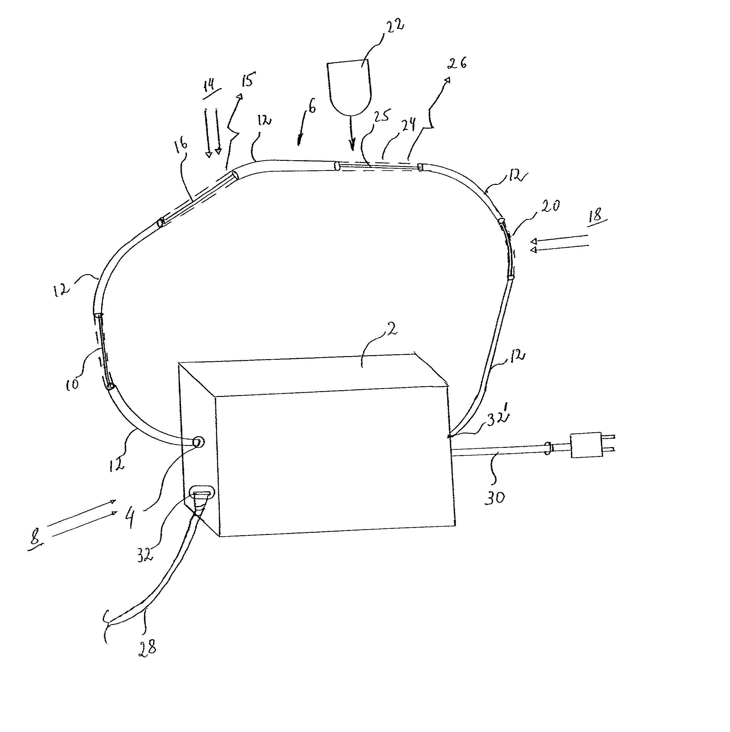
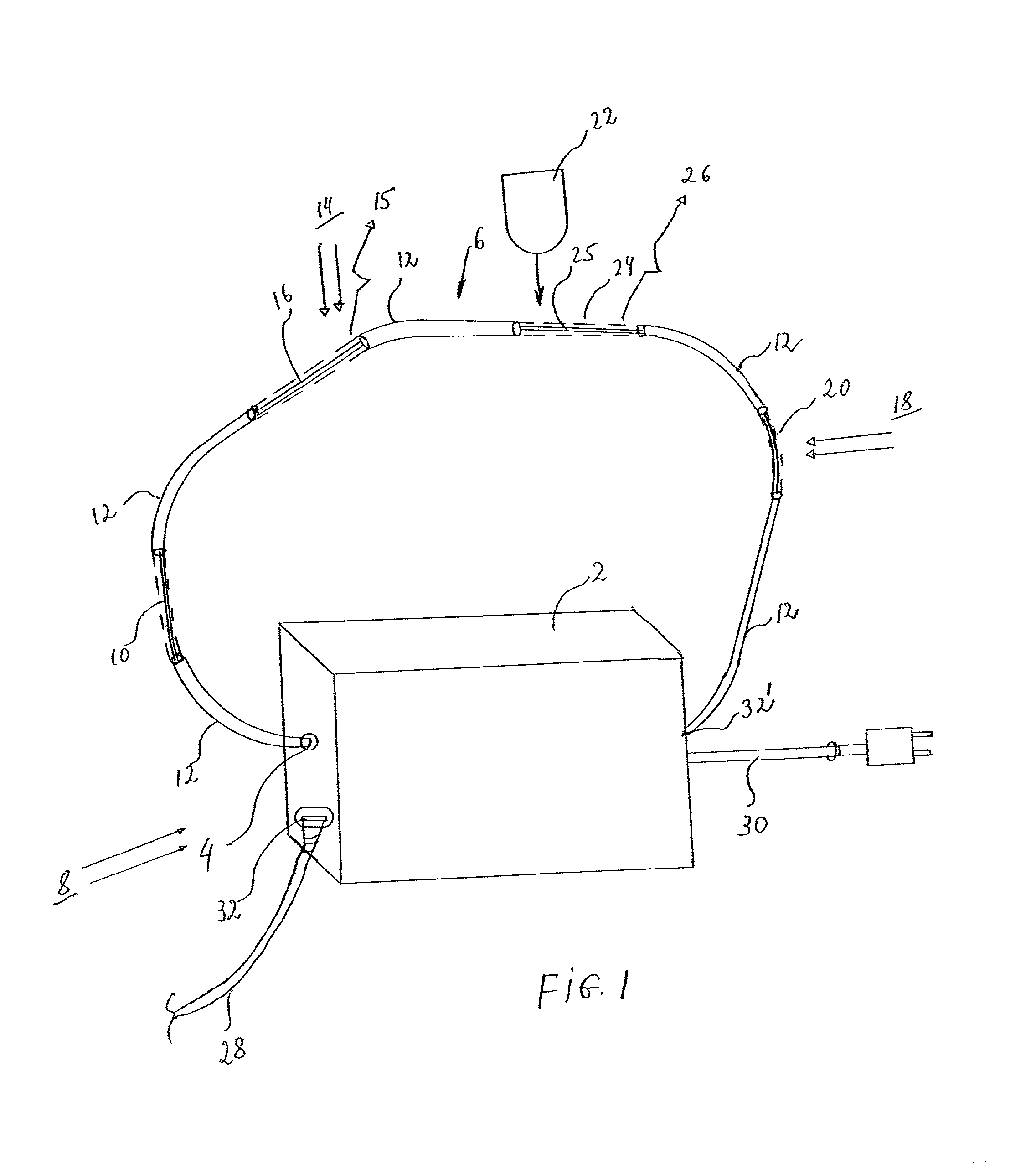
[0046] FIG. 1 represents a distributed radiation sensor according to the present invention. Optical drive and receive unit 2 is controlled by a computer (not shown) via cable 28, for example, a USB connector, which is plugged into cable connector 32, for example, a USB connector. Of course, any interface to a controlling computer may be used, and the unit may be composed of separate subsections which perform the same function. Power for unit 2 is provided by power cable 30. Optical fiber connector 4 connects to an optical fiber, which in this case is sensing fiber 6. Native portions 12 of optical fiber 6 are unmodified, and may, for example, be commercially available silica fiber which transmits light directed therethrough with minimal losses. Native portions 12 have at least one layer of cladding, and may have either a single-mode or multi-mode fiber core.

[0047] First radiation sensing region 10 may be defined as a "core dosimeter" region. Sensing region 10 may be modified as part ...


PUM


Abstract

A distributed fiberoptic radiation sensor is described which may employ one or more radiation sensor elements distributed in a single optical fiber. Such optical fibers may be placed on surfaces, or even within parts, to unobtrusively measure radiation in precise and even difficult to reach locations. Different sensor elements may respond to different radiation types and wavelength ranges, with each sensor element causing a different wavelength of light to be emitted or absorbed within the fiber. By employing an appropriate combination of detection methods at the ends of the fiber, the distributed sensor may provide type and calorimetric discrimination of radiation incident on one or more distinguishable locations. The radiation information thus detected may be integrated, if desired, to obtain corresponding real-time dose information. With such integration, the device becomes a distributed real-time dosimeter. In another embodiment, the particular radiation sensors distributively employed may undergo permanent change in absorption characteristics. Such a device infers a total radiation dose over a particular period by measuring a change in optical response between the beginning and the end of the particular period.

Description

I. BACKGROUND OF THE INVENTION[0001] 1. Field of the Invention[0002] The present invention pertains to sensing devices, particularly sensing devices based upon fiber optic sensors.[0003] 2. Description of the Related Art[0004] Sensing devices are pervasive today, providing the input from the physical world that enables computing power to be harnessed directly to automatically control physical processes and environments. The present invention has application in at least two kinds of sensing: radiation sensing and material presence sensing.[0005] Radiation sensors, as the name implies, sense radiation impinging on a particular locale. Sensing is typically limited to a particular type of radiation, such as .gamma.- or .beta.-radiation, and to a particular frequency or energy range. Some radiation measuring devices provide information about a present radiation rate or intensity; dosimeters, on the other hand, typically provide information about the total radiation encountered over a giv...

Claims


Application Information

Patent Timeline
IPC IPC(8): G01N21/77G01T5/08
CPCG01N21/7703G01T5/08
Inventor ZINCK, JENNIFER J.
Owner HRL LAB
Learn More