Dynamic displays
a technology of dynamic display and transformer, applied in the field of dynamic display, can solve the problems of multiple such transformers, multiplying the complexity, cost and weight of the display, and producing significant r.f.i. (radio frequency interference) and/or e.m.i. (electro-magnetic interference)
- Summary
- Abstract
- Description
- Claims
- Application Information
AI Technical Summary
Benefits of technology
Problems solved by technology
Method used
Image
Examples
first embodiment
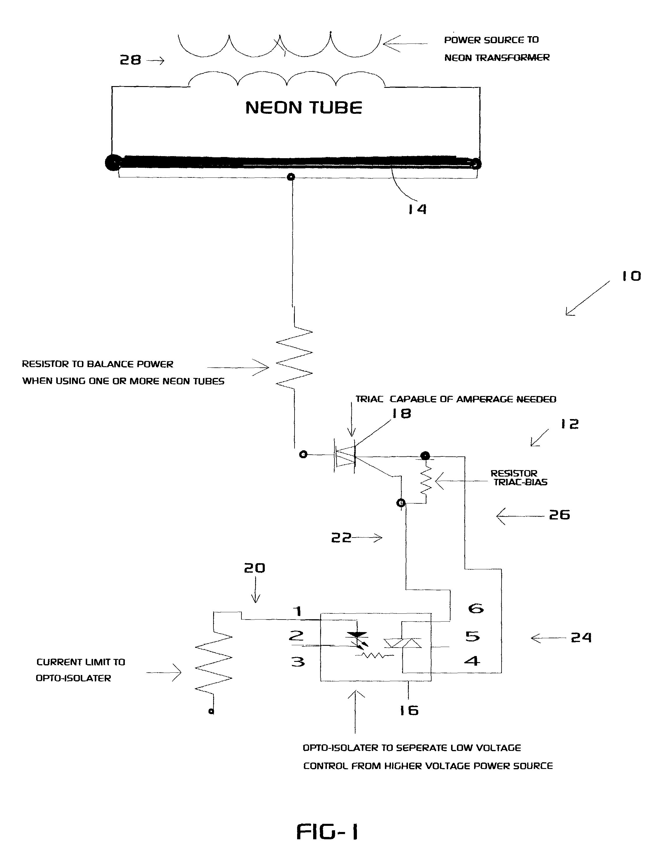
[0019] FIG. 1 shows displays 10 according to the present invention, an isolator / switch 12 which may be combined with others to control operation of tubes 14 in the display 10. Here, the isolator / switch 12 includes an opto-isolator 16 and a triac 18. The opto-isolator 16 (which may be a single component) is used to isolate or separate low power control electronic circuits 20 from higher powered power circuits 22 (hereinafter, "isolate"). The isolator 24, which may be any sort of device that is capable of isolating or separating low voltage control circuits from higher power power circuits, is used in conjunction with a switch 26 that shunts or otherwise removes power from the gas discharge tube 14; in this embodiment, the switch 26 is a triac 18. The switch 26 may be any device, preferably semiconductor, that can accommodate the higher power necessary to illuminate a desired length of gas discharge tube 14 and that preferably switches bidirectionally. Suitable switches 26 which may b...
second embodiment
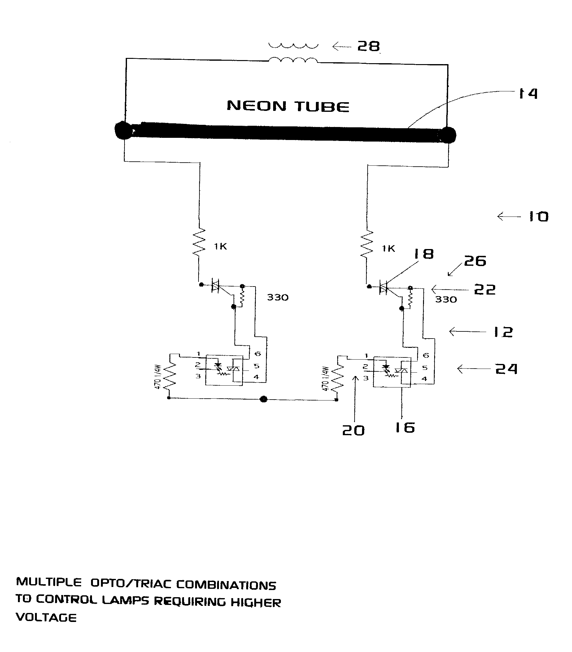
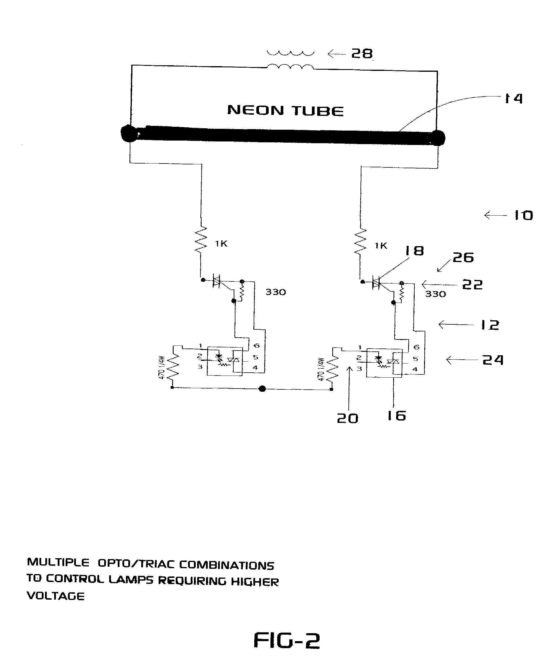
[0021] FIG. 2 shows displays 10 according to the present invention. As the diameter of the tube 14 and / or the tube length varies, voltage requirements to illuminate the tube 14 may increase. When the voltage, current or power requirement exceeds the capability of the isolator / switch 12 (here the opto-isolator / triac combination), the isolator / switch 12 can remain in the shorted / shunted condition not allowing the tube 14 to light. According to the present invention, this situation may be addressed by combining or connecting multiples of the isolator / switches 12 as shown in FIG. 2 (here with high power sides connected in series) or as otherwise desired to increase voltage tolerance, current tolerance, power tolerance, or any of these, to allow for shunting or removing some or all power from tube 14 in order to turn it on and off.
third embodiment
[0022] FIG. 3 shows displays 10 according to the present invention in which three isolator / switches 12 control operation of one tube 14.
PUM
 Abstract
Description
Claims
Application Information
 - R&D
- Intellectual Property
- Life Sciences
- Materials
- Tech Scout
- Unparalleled Data Quality
- Higher Quality Content
- 60% Fewer Hallucinations
Browse by: Latest US Patents, China's latest patents, Technical Efficacy Thesaurus, Application Domain, Technology Topic, Popular Technical Reports.
© 2025 PatSnap. All rights reserved.Legal|Privacy policy|Modern Slavery Act Transparency Statement|Sitemap|About US| Contact US: help@patsnap.com


