Foundation for suction in installation of conductor casing

a technology of conductor casing and foundation, which is applied in the direction of anchors, vessel construction, bulkheads/piles, etc., can solve the problems of encumbered known substructure devices with some disadvantages concerning strength and cost, large washouts of pilot holes, and the inability to fill cement grout, etc., to achieve the effect of reducing the cost of conductor casing, and ensuring strength

Inactive Publication Date: 2003-02-13
NEODRILL
View PDF0 Cites 41 Cited by
  • Summary
  • Abstract
  • Description
  • Claims
  • Application Information

AI Technical Summary

Problems solved by technology

The known substructure devices are encumbered with some disadvantages concerning strength and costs.
The drilling of a pilot hole as described above, and in which the drilling is done in loosely composed and substantially water filled waterbed sediments, often leads to great washouts of the wall of the pilot hole, and the greatest washouts often take place in the upper part of the lead hole.
By subsequent cementing of the conductor casing string, one will often achieve an unsatisfactory filling of cement grout in the expanded tubular space between the wall of the conductor casing string and the pilot hole.
After the cement grout is hardened in the tubular space, this may lead to the load carrying conductor casing string getting an unsatisfactory lateral support for the above loads.
Moreover, the hardened cement grout acts as a safety pressure barrier for possible outflows of e.g. gas in underlying shallow layers of the base formations, and an unsatisfactory cementing can weaken or eliminate this pressure barrier.
In addition, large amounts of cement grout are required for the cementing of a conductor casing string, and the volume increases according to the degree of washing out that has taken place during the drilling of the pilot hole.
The method of first drilling a pilot hole, for then to cement a conductor casing string, may also lead to an unfortunate or unacceptable vertical deviation on the installed conductor casing string, either due to the pilot hole being drilled obliquely down into the seabed, or because the conductor casing string is not kept sufficiently immobile within an acceptable vertical deviation during the time needed for the cement grout to develop sufficient rigidity for supporting the conductor casing string.
The drilling of pilot holes and the following cementing of the conductor casing string is further complicated when in deep water locations.
This has to do with both the conductor casing string being affected by ocean streams and as a consequence of possible drift of a floating drilling installation, but also as a consequence of low seabed temperatures, which may lead to an extremely long hardening period for the cement grout.
The method of first drilling a pilot hole for then to cement a conductor casing string is in this context the main problem, and this method is in addition time consuming and expensive as the work i.a. must be performed with a drilling rig.

Method used


Image

  • Foundation for suction in installation of conductor casing
  • Foundation for suction in installation of conductor casing
  • Foundation for suction in installation of conductor casing

Examples


Embodiment Construction

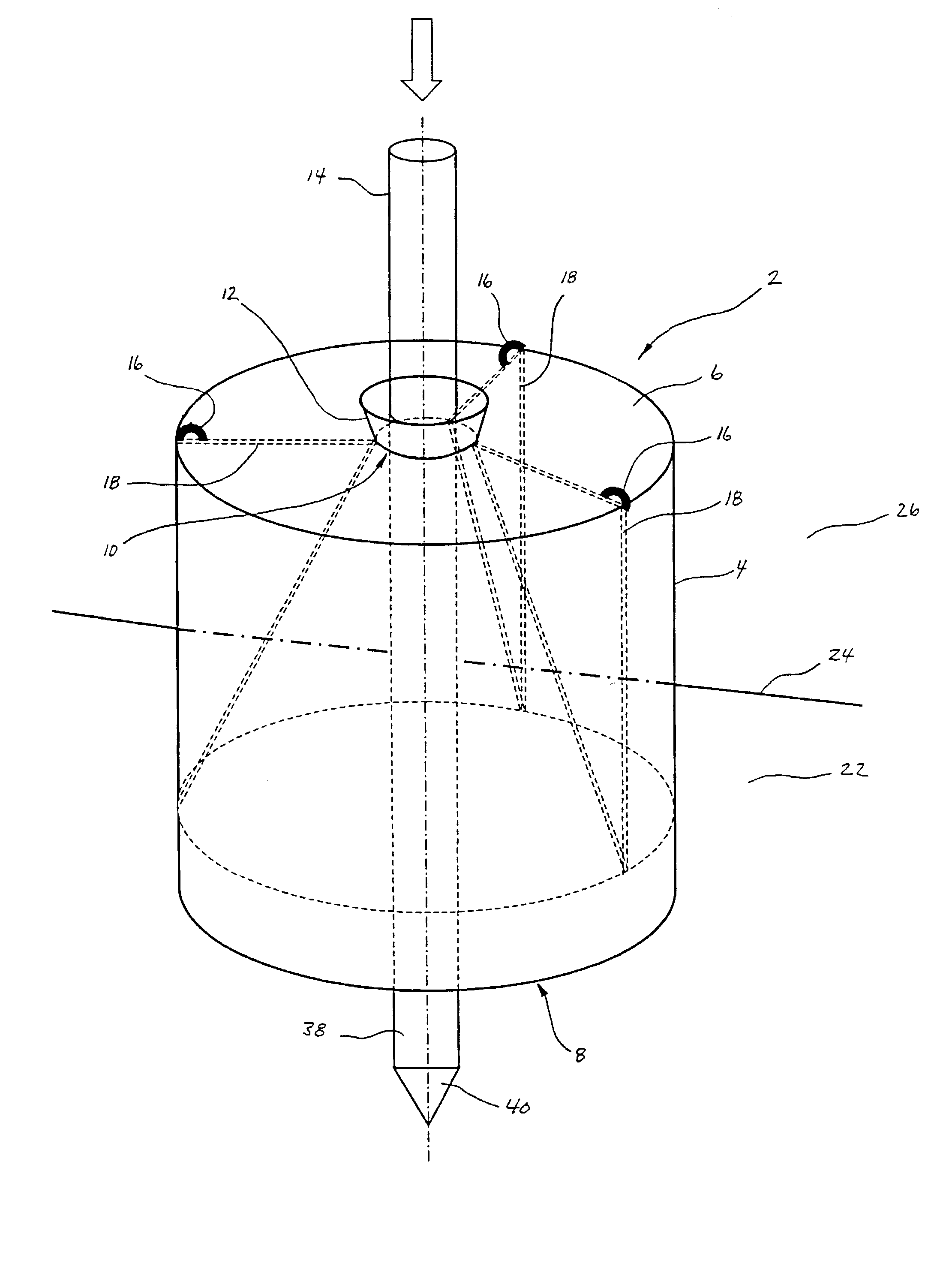
[0038] Equipment and / or arrangement which do not directly apply to the invention itself, but which still are necessary prerequisites for the operation of the invention are not more closely defined or described in detail in the following operating examples. Such equipment and / or arrangement includes e.g. surface vessels, submarine vessels, hoisting equipment, guide lines, pipes and hoses, couplings, valves, pumps, control equipment and possibly other necessary equipment or devices. This is well-known equipment for a person qualified in the field.

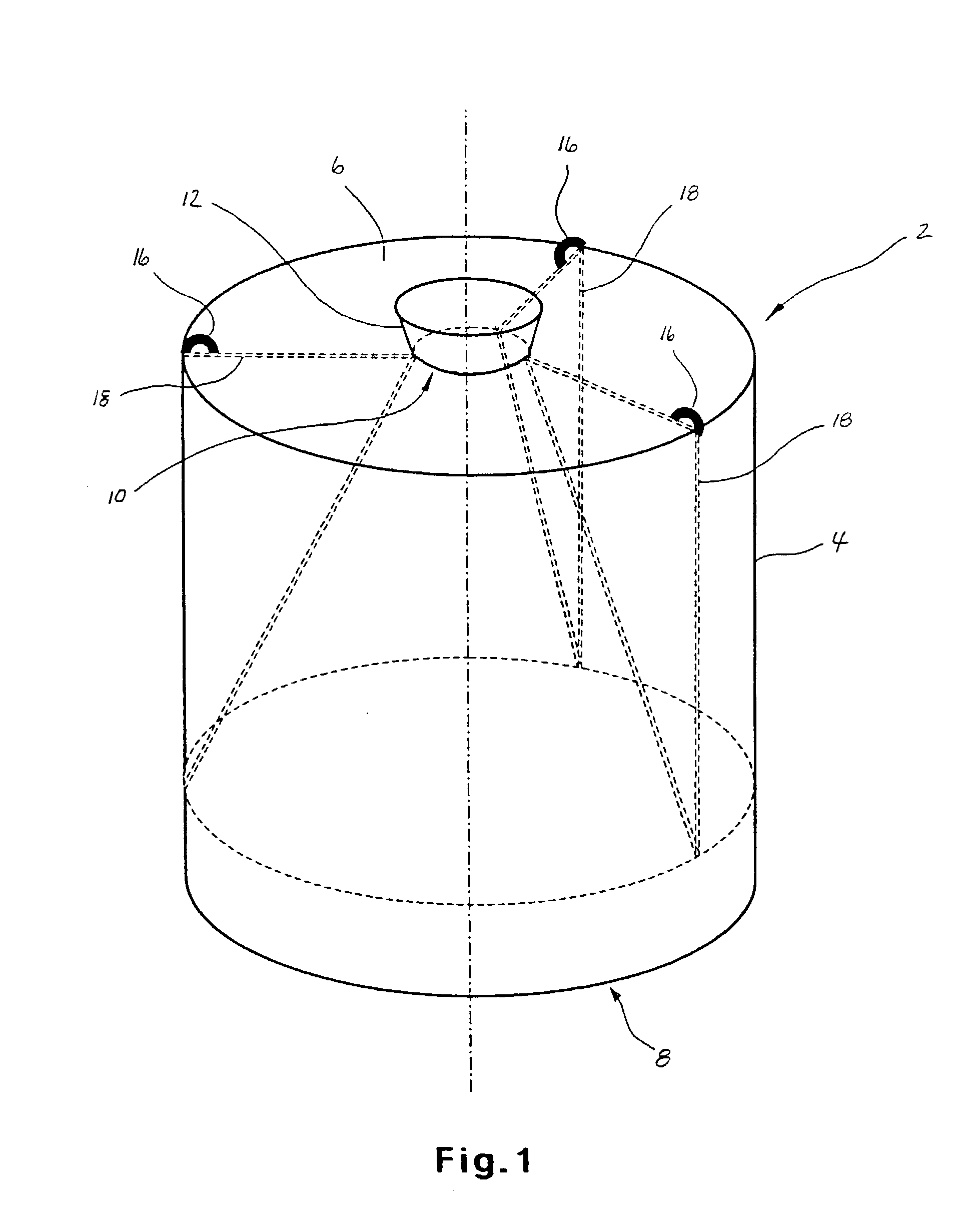
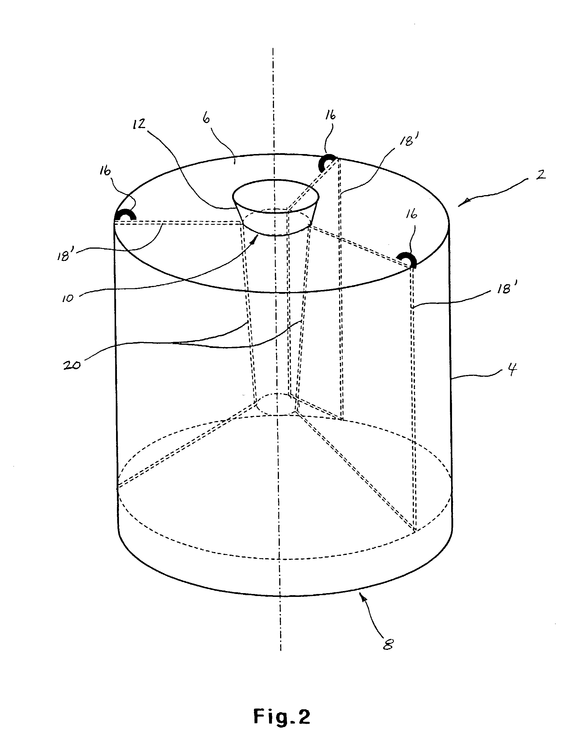
[0039] FIG. 1 and FIG. 2 show a suction substructure 2 formed of a cylinder shaped and encompassing vertical part / mantle 4 being joined in a pressure sealing manner, e.g. by welding, having an upper circular horizontal part / lid part 6, and where the suction substructure 2 is shaped with one in the operating position open end part 8 in the lower end of the suction substructure 2. The lid part 6 is shaped with a through-going guide opening 10, ...


PUM


Abstract

The invention concerns a suction substructure (2) for the setting of one or more conductor casing strings (14) in connection with drilling of at least one underwater well, preferably a petroleum well, and where the use of a suction substructure (2) renders possible the installation of conductor casing by means of known piling technique and by means of a suitable surface vessel, e.g. a suitable boat. The suction substructure (2) consists of a substructure body, which is joined in a pressure sealing manner, and which is shaped with a downwards open end part (8), which is set some way down in the seabed sediments (22). Thereupon water is pumped out of the suction substructure (2), which causes a negative pressure in the suction substructure (2), and where the suction substructure (2) thereby is pressed further down into the seabed sediments (22). The suction substructure (2) is in addition in its upper end fitted with at least one guide opening (10) and possibly an appurtenant guide funnel (12), and an appurtenant releasable and pressure sealing lid (32), and where the guide funnel (12) will be able to guide and give lateral support to a conductor casing string (14) during its subsequent installation.

Description

SCOPE OF THE INVENTION[0001] The invention concerns a substructure device in the shape of a suction substructure and a method for installing it on and in a waterbed as well as use of the suction substructure in connection with installation of conductor casing for one or more wells, preferably petroleum well(s), in which the installation of suction substructure and drilling of wells are performed from e.g. a floating installation.[0002] The background of the invention is the disadvantages of installation and costs often experienced with the use of known substructure devices in connection with the drilling of underwater wells.KNOWN TECHNIQUE[0003] In connection with known technique the work with a new well is normally started by the drilling of a pilot hole from a drilling installation, e.g. a drilling rig, the hole having a diameter of e.g. 36", down to a suitable depth under the waterbed, typically approx. 70 metres. In the description that follows the waterbed will be referred to a...

Claims


Application Information

Patent Timeline
Patent Type & Authority Applications(United States)
IPC IPC(8): E21B7/12E21B7/20E21B19/24E21B41/00
CPCE21B7/12E21B7/20E21B19/24E21B41/0014E21B33/02E21B41/0007
Inventor STRAND
Owner NEODRILL
Why Eureka
Try Eureka