Separation process and apparatus

a separation process and apparatus technology, applied in separation processes, lighting and heating apparatus, furniture, etc., can solve the problems of material cost, erosion of downstream equipment, and two-fold loss of catalysts that are not recovered from the fcc process

Inactive Publication Date: 2003-02-13
UOP LLC
View PDF16 Cites 11 Cited by
  • Summary
  • Abstract
  • Description
  • Claims
  • Application Information

AI Technical Summary

Benefits of technology

[0013] It has now been discovered that by orienting the angular direction of a swirl motion from a VSS.sup.SM to counter the angular direction of a swirl motion in a downstream cyclone enhances the separation efficiency. When the swirl motions in the VSS.sup.SM and the cyclones are oriented to agree, the mixture entering into the cyclone is less likely to first encounter the interior surface of the outer wall, which imparts the swirl motion to the mixture. Instead, the mixture is more likely to encounter a center of the cyclone where the inlet to the vapor outlet conduit is located. Consequently, some of the mixture entering the cyclone is permitted to exit the cyclone before a swirl motion is imparted to the mixture by the outer wall. Under these circumstances, some of the mixture exits the cyclone with minimal further separation of solid particles from the gaseous vapors. It has been discovered that by orienting the angular direction of the swirl motion from the VSS.sup.SM to be counter to the angular direction of the swirl motion in the cyclones, the mixture entering the cyclone is more likely to first encounter the outer wall, thereby imparting to the mixture a swirl motion before the mixture can encounter the center of the cyclone. Accordingly, greater separation efficiency results. To achieve counter-direction of swirl motions, the curvature of the VSS.sup.SM swirl arm is oriented so that the opening at the end of the swirl arm angularly faces toward the wall of the inlet to the cyclone that is contiguous with the curved wall of the cyclone.
[0014] Accordingly, in one embodiment, the present invention relates to a process for the fluidized catalytic cracking of a hydrocarbon feedstock comprising passing a hydrocarbon feedstock and solid catalyst particles into a reaction conduit to produce a mixture of solid catalyst particles and gaseous fluids. The mixture of the catalyst particles and gaseous fluids is induced to swirl in a first angular direction to decrease the catalyst particle concentration and increase the gaseous fluids concentration in the mixture. The mixture is transported to at least one cyclone wherein it is induced to swirl in a second angular direction that is counter to the first angular direction to further decrease the catalyst particle concentration and further increase the gaseous fluids concentration in the mixture.

Problems solved by technology

Additionally, catalyst that is not recovered from the FCC process represent a two-fold loss.
The catalyst must be replaced, representing a material cost, and catalyst lost may cause erosion to downstream equipment.
Severe erosion may cause equipment failure and subsequent lost production time.

Method used


Image

  • Separation process and apparatus
  • Separation process and apparatus
  • Separation process and apparatus

Examples


Embodiment Construction

[0032] Computational flow dynamics (CFD) modeling using a FLUENT program was performed to study separation efficiencies for three sets of conditions. The following was assumed for all three sets of conditions: the minimum catalyst size was 40 micrometers, the gas density was 2.75 kg / m.sup.3, the gas velocity was 0.02 c.p., the velocity of the mixture exiting each swirl arm was 20.8 m / sec, the pressure was 299 kPa and the temperature was 549.degree. C.

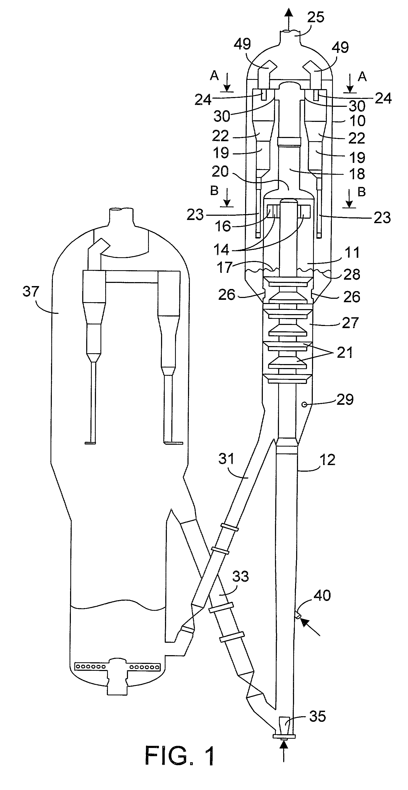
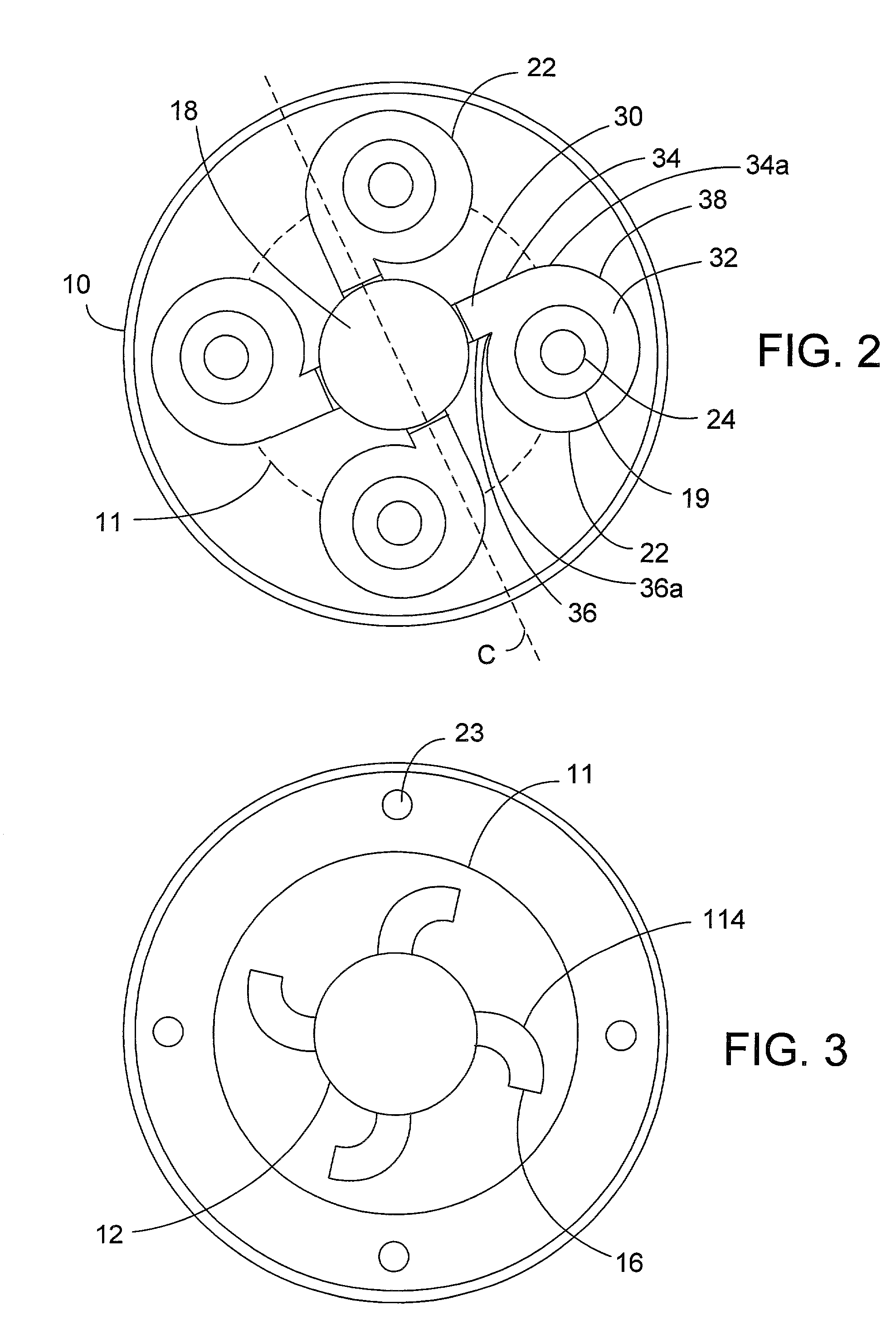
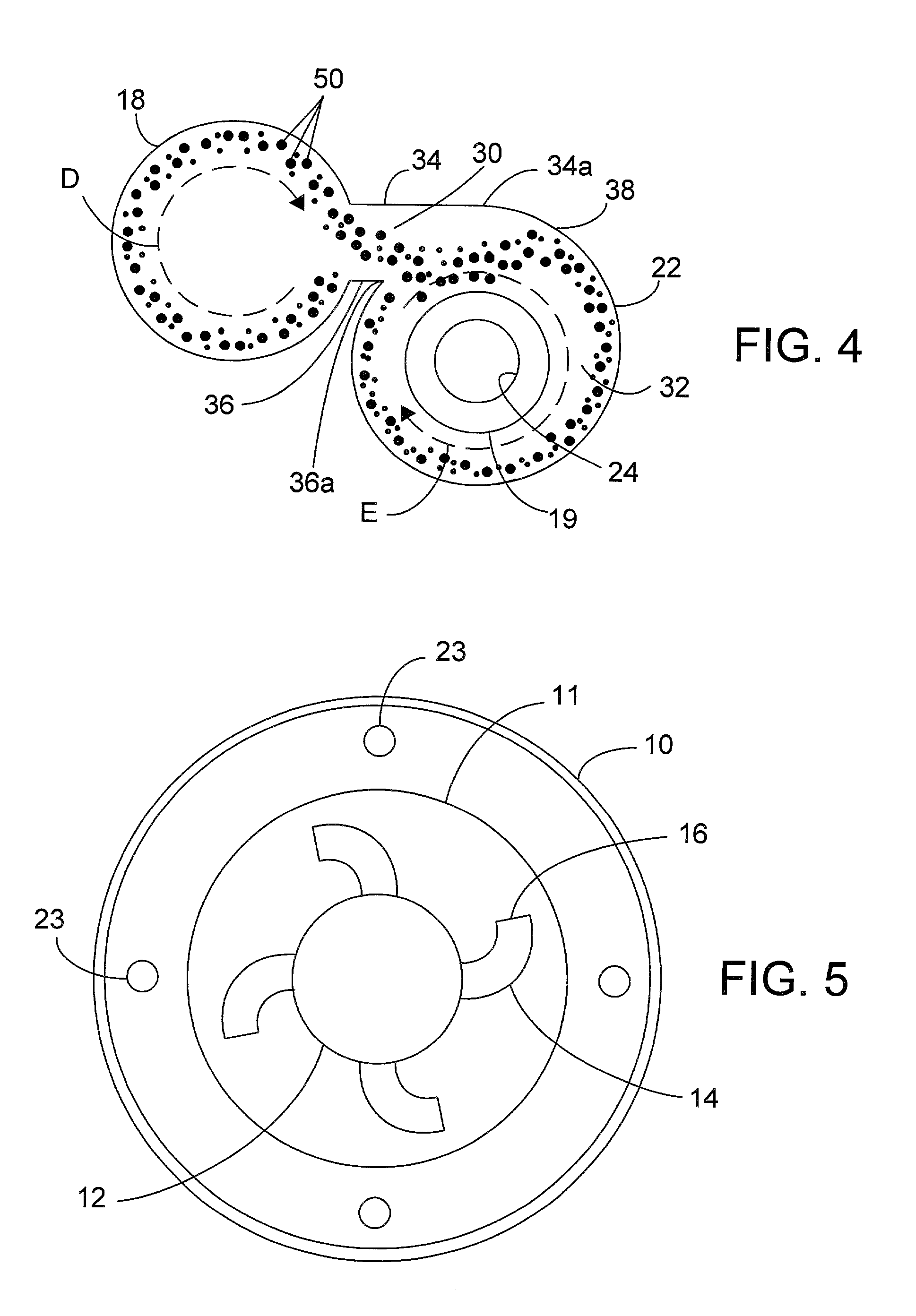
[0033] The first set of conditions involved a model where radial cyclone inlets 30 to the cyclones 22 were disposed with respect to the gas recovery conduit 18 as shown in FIG. 2 and the swirl arms 114 were disposed as in FIG. 3. This model focused on the case where the angular direction of the swirl motion imparted by the swirl arms was the same as the angular direction of the swirl motion imparted by the cyclones 22 as shown in FIG. 4. The CFD modeling indicated that in this model, 21% of the mixture entering the cyclone veered toward...


PUM

PropertyMeasurementUnit
temperatureaaaaaaaaaa
pressureaaaaaaaaaa
velocityaaaaaaaaaa

Abstract

An apparatus and process is disclosed for the separation of solids from gases in a mixture which is most particularly applicable to an FCC apparatus. The mixture of solids and gases are passed through a conduit and exit through a swirl arm that imparts a swirl motion having a first annular direction to centripetally separate the heavier solids from the lighter gases. The mixture then enters a cyclone which has a curved outer wall and imparts a second swirling angular direction to the mixture. The second angular direction is counter to the first angular direction. The apparatus and method assures that a greater proportion of the mixture entering the cyclone is incorporated into the vortex to further enhance separation between the solids and gases.

Description

[0001] This invention relates generally to an apparatus and a process for the separation of solid particles from gases. More specifically, this invention relates to the separation of particulate catalyst materials from gaseous materials in an FCC process.DESCRIPTION OF THE PRIOR ART[0002] Cyclonic methods for the separation of solids from gases are well known and commonly used. A particularly well known application of such methods is in the hydrocarbon processing industry where particulate catalysts contact gaseous reactants to effect chemical conversion of the gas stream components or physical changes in the particles undergoing contact with the gas stream.[0003] The FCC process presents a familiar example of a process that uses gas streams to contact a finely divided stream of catalyst particles and effects contact between the gas and the particles. The FCC processes, as well as separation devices used therein are fully described in U.S. Pat. Nos. 4,701,307 B1 and 4,792,437 B1, th...

Claims


Application Information

Patent Timeline
Patent Type & Authority Applications(United States)
IPC IPC(8): B01J8/00B01J8/26C10G11/18
CPCB01J8/0055B01J8/26C10G11/18
Inventor NIEWIEDZIAL, STEVENMYERS, DANIEL N.
Owner UOP LLC
Why Eureka
Try Eureka