Spinal cord removal tool with adjustable blades

a technology for removing tools and spinal cords, applied in the field of spinal cord removal tools, can solve the problems of affecting the operation of the tool and the proper removal, affecting the removal of spinal cords, and elongating the spinal cord membrane, so as to achieve accurate control, increase the support of the blade, and operate at a higher speed

Inactive Publication Date: 2003-03-06
JARVIS PROD
View PDF2 Cites 7 Cited by
  • Summary
  • Abstract
  • Description
  • Claims
  • Application Information

AI Technical Summary

Benefits of technology

[0015] In a first embodiment the right and left side adjustment mechanisms are self-adjusting and provide a floating mount for the side blades. In this embodiment, the side blades are straight and always contact at least two edges of the removal blades. The side blades are urged towards the side cutting edges of the removal blades by one or more springs. The floating spring mounting of the side blades allows them to automatically compensate for any changes in the location of the cutting edges due to wear or sharpening.
[0016] In a second embodiment the right and left side blades are curved and are always in contact with at least three edges of the removal blades. Each side blade is preferably urged towards the facing side cutting edges of the removal blades by three springs, which provide three floating mounts for each blade. The additional curved length of the side blades and the additional contact with the side cutting edges of the removal blades provides more blade support and allows the tool to operate at higher speeds.
[0017] In a third embodiment of the invention the right and left side adjustment mechanisms comprises right and left side manual adjustment mechanisms, which include corresponding right and left side adjustment screws for moving the right and left side blades towards and away from the cutting edges of the spinal cord removal blades. Preferably, the side blades are straight and include a pair of adjustment screws, located at each end, with corresponding lock screws for locking the adjustment after it has been set manually. The manual adjustment allows the clearance between the side blades and the removal blades to be very accurately controlled and adjusted for improved cutting performance, reduced blade chatter and low noise, particularly when the tool is operated at very high speeds.

Problems solved by technology

Complete removal of the spinal cord is difficult due to the many irregularities and protrusions in the bony channel that surrounds it.
A related problem is the elongated spinal cord membrane, which tends to wrap around the shaft of motorized removal tools and interfere with operation of the tool and proper removal of the spinal cord.
One difficulty with the tool shown in EP 0 890 313 B1 is the fixed location of the side blades relative to the side edges of the removal blades.
Because the side blades are located a fixed distance apart, it is difficult to manufacture the tool.

Method used


Image

  • Spinal cord removal tool with adjustable blades
  • Spinal cord removal tool with adjustable blades
  • Spinal cord removal tool with adjustable blades

Examples


second embodiment

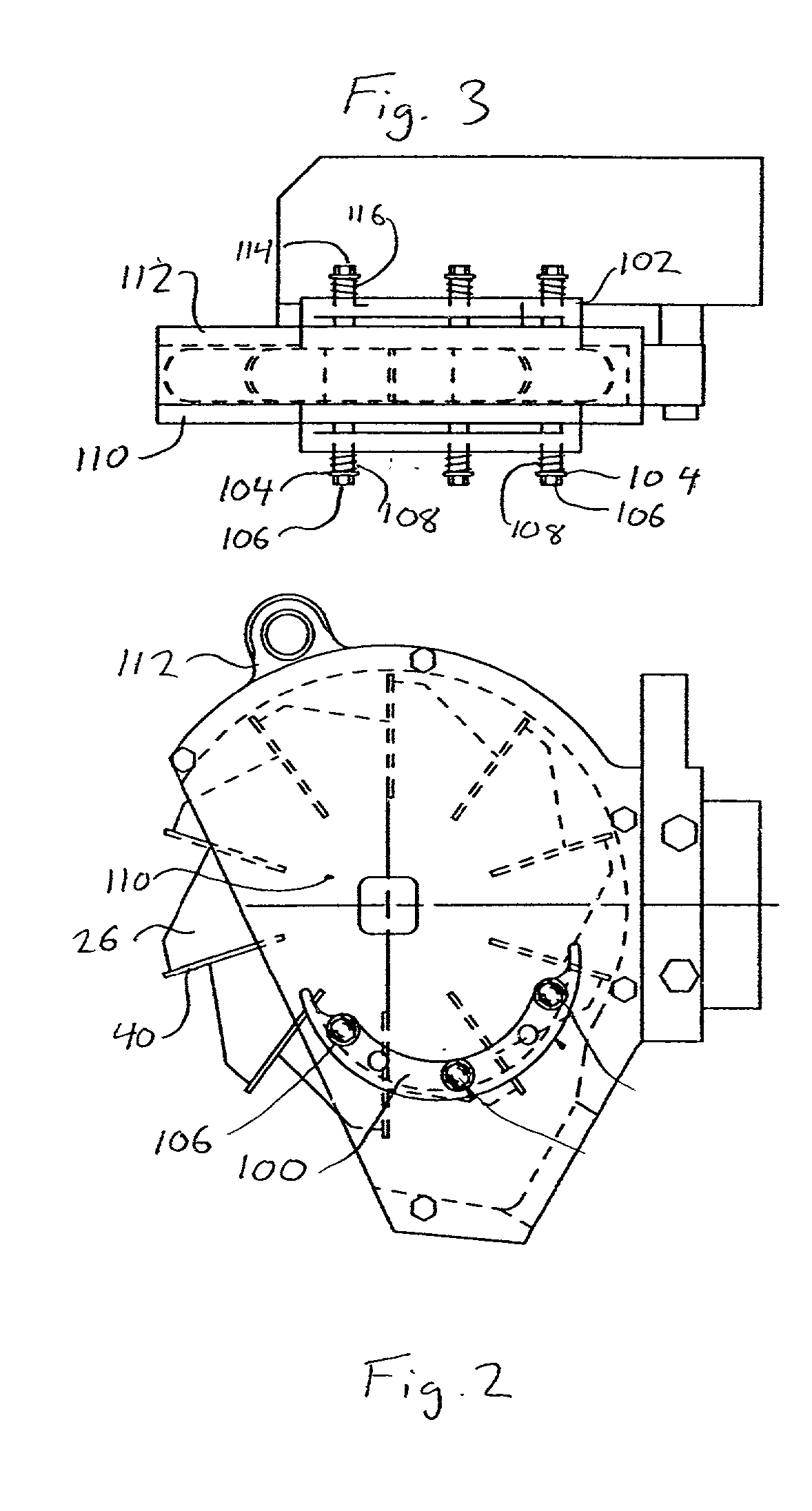
[0041] FIGS. 2-3 illustrate the present invention. In this design the left and right side blades 100 and 102 are curved and are always in contact with at least three of the side cutting edges 48, 50 on the removal blades. This additional contact provides greater blade stability during high-speed operation and reduces the likelihood of blade chatter. The right and left side adjustment mechanisms for the curved side blades 100 and 102 are similar to the adjustment mechanism described in connection with the straight blades shown in FIG. 1 except that three mounts are used, instead of two, and the function of support plate 82 has been replaced by an enlarged head 104 on the mounting screws 106.

[0042] The left side adjustment mechanism includes three left side mounting screws 106 with corresponding left side springs 108. The left side mounting screws 106 are threaded into the cover 110 which includes a curved slot to receive the curved cutting edge of the left side blade 100. The curved ...

third embodiment

[0046] FIGS. 4-6 show the present invention in which the side blades 200 and 202 are straight, similar to the design in FIG. 1, but the right and left adjustment mechanisms hold the side blades in a fixed location, instead of allowing them to float as in the two previously described embodiments of the invention. The side blades in this design are manually adjustable towards and away from the side cutting edges 48 and 50 on the blade disk. This allows the side blades to be adjusted to minimize or eliminate any blade chatter during the highest operation speeds. It also helps to minimize blade noise resulting from contact between the side blades and the side edges of the removal blades during high-speed operation.

[0047] In this design the side blades 200 and 202 include internally threaded openings 204 that receive adjustment screws 206. The adjustment screws 206 are externally threaded to match the internal thread of openings 204 in the side blades. The adjustment screws 206 are also ...


PUM


Abstract

A spinal cord removal tool for removing a spinal cord and spinal cord membrane from a carcass includes a spinning blade disk having multiple removal blades mounted around its perimeter, each removal blade having a forward facing cutting edge that can enter the spinal cord channel and side cutting edges that cooperate with side blades to chop the spinal cord membrane as it is brought into the tool. The side blades are adjustably mounted to move towards and away from the removal blades and compensate for changes in the width of the removal blades due to wear or sharpening. The side blade adjustment mechanism may include a self-adjusting floating mount for the side blades or a manually adjustable mount that can be set to any desired blade clearance for higher-speed and lower noise operation.

Description

[0001] 1. Field of the Invention[0002] The present invention relates to tools for removing the spinal cord from carcasses.[0003] 2. Description of Related Art[0004] Spinal cord removal tools are used in the processing of carcasses to remove the spinal cord from the spinal cord channel surrounding it. Complete removal of the spinal cord is difficult due to the many irregularities and protrusions in the bony channel that surrounds it. Accordingly, tools of this type must perform both a cutting and grinding action and may also be referred to as "spinal cord grinders." A related problem is the elongated spinal cord membrane, which tends to wrap around the shaft of motorized removal tools and interfere with operation of the tool and proper removal of the spinal cord.[0005] One tool that addresses these problems in removing the spinal cord is seen in European Patent EP 0 890 313 B1, which uses a motor driven blade disk spinning inside a housing. The blade disk includes multiple spinal cor...

Claims


Application Information

Patent Timeline
Patent Type & Authority Applications(United States)
IPC IPC(8): A22B5/00
CPCA22B5/0005A22B5/201A61B17/56
Inventor GWYTHER, PETER
Owner JARVIS PROD
Why Eureka
Try Eureka