Venting valve assembly for castings moulds

Inactive Publication Date: 2003-03-27
FONDAREX
View PDF3 Cites 14 Cited by
  • Summary
  • Abstract
  • Description
  • Claims
  • Application Information

AI Technical Summary

Benefits of technology

0009] Therefore, it is an object of the present invention to provide a venting valve assembly for casting moulds which can be universally used due to the fact that its closure element is moved very qui

Problems solved by technology

With such a venting valve assembly, the valve closure member can be brought into its closed position extremely quickly, because the time require

Method used


Image

  • Venting valve assembly for castings moulds
  • Venting valve assembly for castings moulds
  • Venting valve assembly for castings moulds

Examples


Embodiment Construction

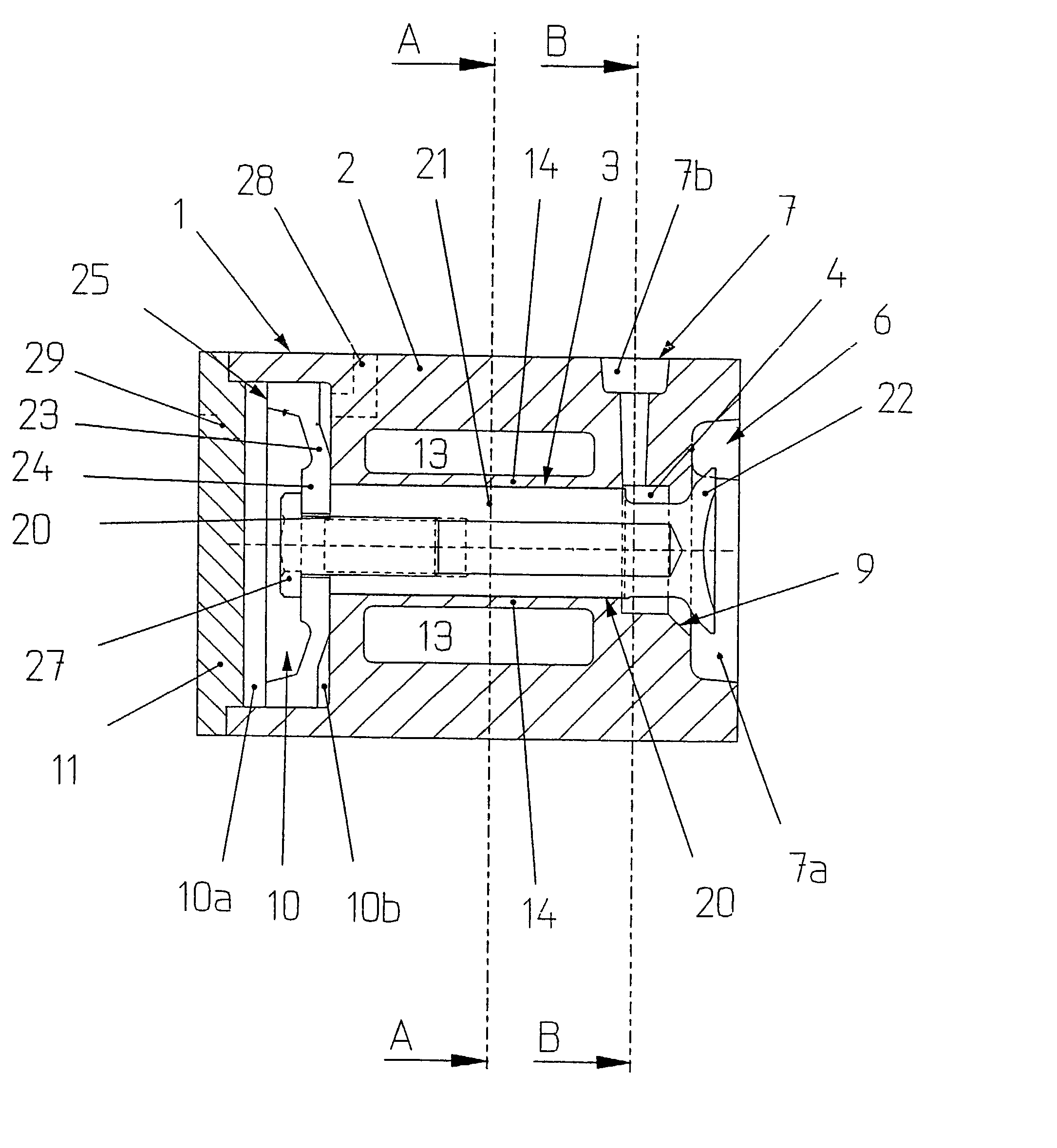
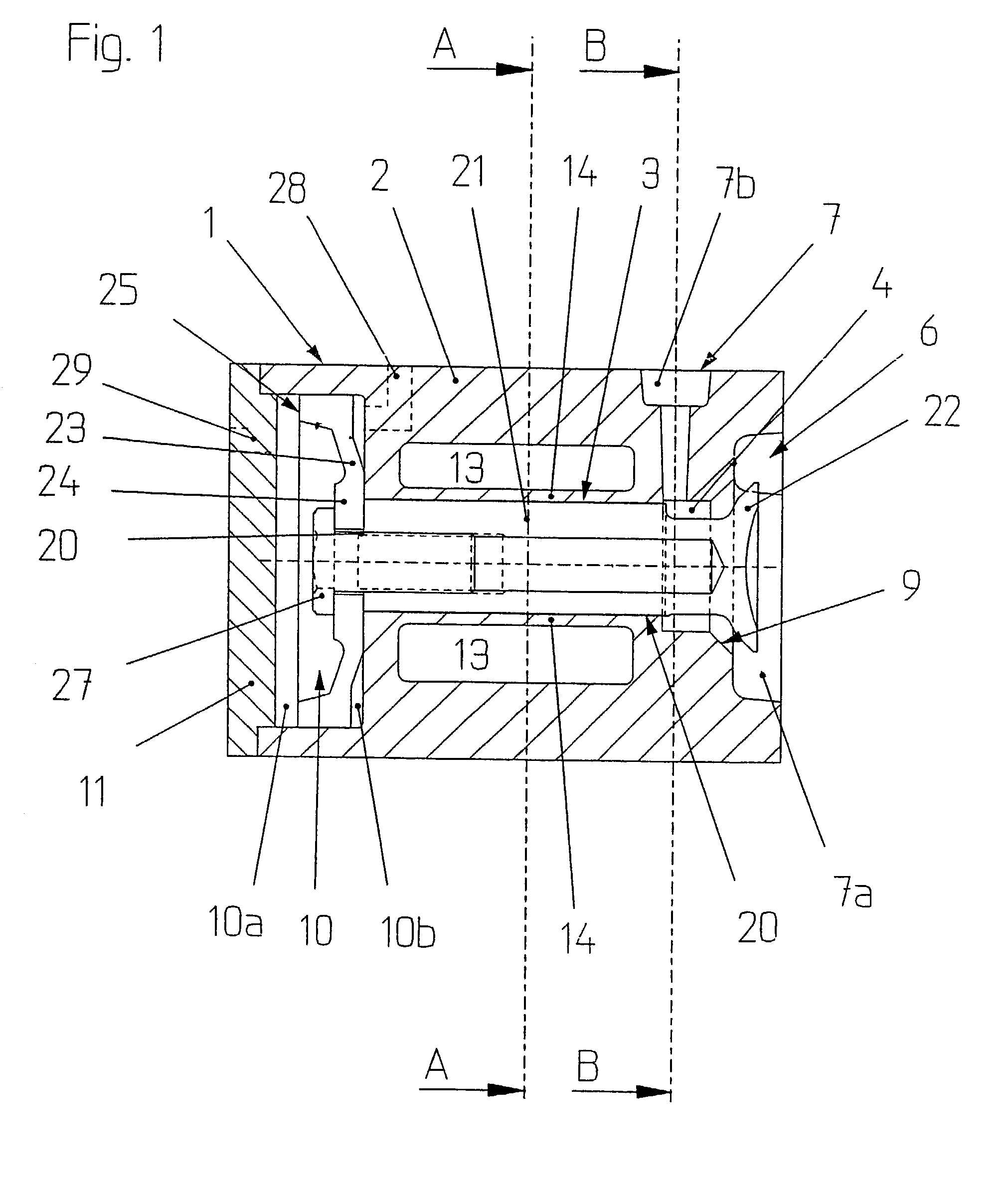
[0020] FIG. 1 shows a longitudinal sectional view of a venting valve 1, and the general design thereof shall be further explained with the aid of this illustration. As can be seen in the drawing, the venting valve 1 comprises a round valve housing 2 having a central valve channel 3 adapted to receive and guide a closure member 20. The front end of the valve housing 2, i.e. the right side thereof as seen in FIG. 1, is provided with a venting chamber 6 communicating with a venting channel 7. Moreover, the venting chamber 6 also communicates with the valve channel via a valve seat 9.

[0021] The venting chamber 6 is located between a first portion 7a of the valve channel 7, communicating with the cavity of the casting mould (not shown) to be vented, and a second portion 7b of the venting channel 7 opening at the upper side of the valve housing 2. The above mentioned second portion 7b of the venting channel 7 radially opens into a valve chamber 4 located upstream of the valve channel 3 an...


PUM

PropertyMeasurementUnit
Pressureaaaaaaaaaa
Shapeaaaaaaaaaa
Elasticityaaaaaaaaaa

Abstract

The venting valve assembly for casting moulds comprises a venting valve for closing a venting channel. The venting valve comprises a valve housing in which a closure member is received that is movable between an open position and a closed position. The closure member can be frictionally locked in its open position and simultaneously biased in closing direction. For frictionally locking the closure member, a chamber is provided that can be put under a hydraulic overpressure. The chamber has a wall portion that bulges towards the closure member in response to the overpressure. The wall portion is resilient such that it moves back to a position releasing the closure member once the overpressure in the chamber is reduced. For reducing the pressure in the chamber, a release valve is provided which is controlled by a sensor detecting any casting material penetrating into the venting channel. The biasing of the closure member in closing direction is performed pneumatically.

Description

[0001] The present invention refers to a venting valve assembly for casting moulds, comprising a venting valve having a valve housing, a venting channel located in the interior of the valve housing, and a valve closure member located in the interior of the valve housing and adapted to move between an open position and a closed position.[0002] In order to reliably avoid the occurrence of air inclusions in the finished casting during the casting operation, the mould and the cavity in the mould, respectively, have to be vented during the casting operation. Thereby, not only the air contained in the cavity of the mould has to be allowed to escape, but in addition it must be ensured that also the gases escaping from the liquid casting material are removed from the mould cavity.[0003] One of the problems in connection with venting die casting moulds can be seen in the requirement that the venting valve of the valve assembly be closed as late as possible in order to ensure that the mould c...

Claims


Application Information

Patent Timeline
IPC IPC(8): B22C9/00B22D17/22B22C9/06B22D17/14B22D17/20
CPCB22D17/145B22D17/20
Inventor WUTHRICH, ANDREAS
Owner FONDAREX
Why Eureka
Try Eureka