
Control valve for an injector of a fuel Injection system for internal combustion engines with pressure amplification in the control chamber

a technology of control valve and fuel injection system, which is applied in the direction of fuel injection apparatus, machine/engine, feed system, etc., can solve the problem of reducing the closing speed of the nozzle needl

Inactive Publication Date: 2003-03-27
ROBERT BOSCH GMBH
View PDF5 Cites 26 Cited by
  • Summary
  • Abstract
  • Description
  • Claims
  • Application Information

AI Technical Summary

Benefits of technology

[0005] The control valve of the invention has the advantage that with the aid of a portion of the displacement motion of the control valve, positive displacement work is done in the control chamber, and thus the pressure in the control chamber is elevated by the displacement motion. As the result, a steeper pressure rise is obtained in the control chamber upon closure of the control valve, and thus also a steeper rise in the closing force acting on the nozzle needle. As a consequence, the closing duration is shortened. Because of the shortened closing duration, preinjection quantities can be metered more precisely, and the control of the main injection can also be done more accurately and with greater degrees of freedom.
[0006] In a variant of the invention, it is provided that the final control element and a bore of the housing form an annular chamber, whose first end communicates hydraulically with the fuel return and whose second end communicates hydraulically with the control chamber, and that the final control element is axially displaceable by means of a tappet guided in a first guide bore and has means for sealing off the annular chamber from the control chamber. In an alternative embodiment, the final control element has means for sealing off the annular chamber from the fuel return, so that the control valve of the invention can be achieved on the basis of a 2 / 2-way control valve or on the basis of a 2 / 3-way control valve.

Problems solved by technology

However, the closing speed of the nozzle needle is reduced by this provision, since an overcompensation for the hydraulic forces in the direction of the closing motion of the nozzle needle is not possible.

Method used


Image

  • Control valve for an injector of a fuel Injection system for internal combustion engines with pressure amplification in the control chamber
  • Control valve for an injector of a fuel Injection system for internal combustion engines with pressure amplification in the control chamber
  • Control valve for an injector of a fuel Injection system for internal combustion engines with pressure amplification in the control chamber

Examples


Embodiment Construction

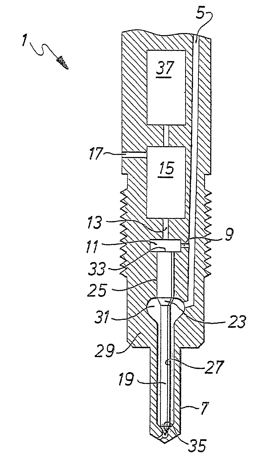
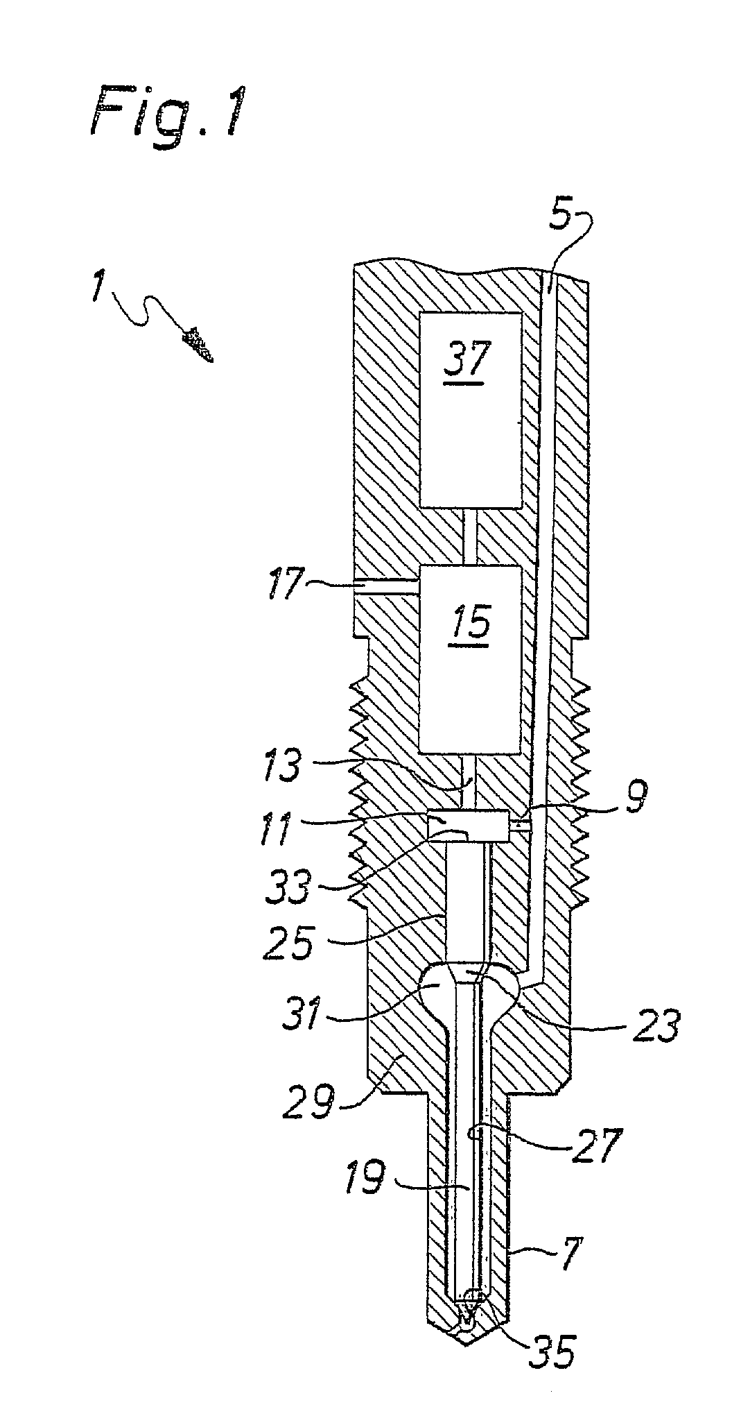
[0023] In FIG. 1, an injector 1 of the invention is shown. Via a high-pressure connection, not shown, fuel is delivered via an inlet conduit 5 to an injection nozzle 7 and via an inlet throttle 9 to a control chamber 11. The control chamber 11 communicates indirectly with a fuel return 17 via an outflow conduit, shown only schematically, with an outlet throttle 13 and via a schematically illustrated control valve 15.

[0024] The control chamber 11 is defined by a nozzle needle 19. The nozzle needle 19 prevents the fuel, which is under pressure, from flowing into the combustion chamber, not shown, between injections. The nozzle needle 19 has a cross-sectional change 23 from a larger diameter 25 to a smaller diameter 27. The nozzle needle 19 is guided with its larger diameter 25 in a housing 29. The cross-sectional change 23 defines a pressure chamber 31 of the injection nozzle 7.

[0025] When the outlet throttle 13 is closed, the hydraulic force exerted on an end face 33 of the nozzle ne...


PUM


Abstract

A control valve (15) for injectors of injection systems for internal combustion engines is proposed, in which part of the displacement path of the final control element (45) serves the purpose of pressure elevation in the control chamber (11). The closing times of the nozzle needle (19) are thereby reduced.

Description

PRIOR ART[0001] The invention relates to a control valve for the injector of a fuel injection system for internal combustion engines as generically defined by the preamble to claim 1 and to an injector for a fuel injection system for internal combustion engines as generically defined by the preamble to coordinate claim 15.[0002] As technology becomes increasingly sophisticated, it is a goal to make the control valves of injectors, and the injectors themselves, as compact as possible and at the same time to achieve short closing times. From European Patent Disclosure EP 0 740 068 A2, an injector is known in which the control chamber is defined by an end face of the nozzle needle. A compact design can be achieved in this way. However, the closing speed of the nozzle needle is reduced by this provision, since an overcompensation for the hydraulic forces in the direction of the closing motion of the nozzle needle is not possible.[0003] The object of the invention is to furnish a control...

Claims


Application Information

Patent Timeline
IPC IPC(8): F02M61/16F02M45/08F02M45/12F02M47/00F02M47/02F02M51/06F02M59/46F02M61/10F02M61/20F02M63/00
CPCF02M45/08F02M45/12F02M47/02F02M47/025F02M47/027F02M59/46F02M63/0026
Inventor BOECKING, FRIEDRICH
Owner ROBERT BOSCH GMBH
Learn More